
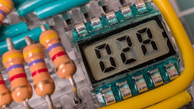
If you’re not aware, there is such a thing as adorable little three digit LCD 7-segment displays. They come in a ten-pin DIP package and are just begging to be integrated into a project. The catch is they are just a tiny bit weird. Luckily for us all, [Nagy Krisztián] spells out exactly how to use them.
The first odd thing about these ten-pin LCD displays is that they have a footprint that doesn’t quite mesh with standard 0.1 inch spacing, meaning they will not cleanly fit into a breadboard. Luckily, one can solve this with a bit of force. It’s a small part, and the pins don’t seem to mind.
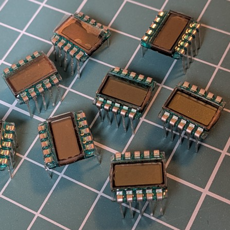
The second odd thing is wrapping one’s head around the pin mapping. Figuring out the table of which pins activate which segments in the digits is easier if one keeps in mind that each segment of each digit is the product of two different pins. For example, “2A” is digit two, segment A, and is the product of pins 3 and COM4.
That’s not all. Electrically speaking, driving this LCD isn’t nearly as straightforward as an LED.
With an LED display, the COM pins are either common anode or common cathode, which tells one whether lighting up a segment means holding the COM pin at GND with voltage applied to the segment pin, or the other way around. But in the case of this LCD display, the polarity applied is swapped every cycle. Oh, and inactive COM pins need to held at half-voltage. Neat!
[Nagy] drives the whole thing with little more than an ATtiny84 microcontroller and a few resistors. A switchable half-voltage signal is cleverly created by combining a simple voltage divider and taking advantage of the fact that the ATtiny84’s pins can be in one of three different states depending on how they are configured: high, low, or high-impedance (pin configured as an input). Each COM pin on the display gets connected to both an ATtiny84 pin, and to the supply voltage via two resistors forming a voltage divider. When the ATtiny drives the pin high, the LCD pin sees about 3 V. When the pin is driven LOW, the LCD pin sees 0 V. When the ATtiny configures the pin as an input, the LCD pin receives about 1.5 V.
The bulk of the software is defining which pins and states equal which digits, and cycling the LCD at a rate of vaguely 60 Hz which delivers flicker-free results.
We appreciate the clever combination of voltage divider with pin configuration to create three switchable voltage levels. If you liked that and want to see more serious leveraging of pin configuration on a microcontroller, check out how to drive seven LEDs with only two pins.












If these are like other multiplexed LCDs, note that the duty cycle normal and inverted drive signals needs to be the same, or the display will see it as a DC bias and slowly electroplate one electrode to another.
Good tip, also why someone knowledgable is around: Are these worth my time? As in, is the current draw significantly better to bother with this specific type and model?
P/N?
Yeah, I kinda want to find some of these now, though, I have no idea what I would only use 3 digits for…
Aliexpress has them, their image search finds them easily if you submit the picture in this article. There’s also a 6 digit one that looks like a bigger version of this one: search “16PIN TN Positive 6-Digits”, but definitely the driving system is a bit cumbersome for so many digits: if I had to choose I’d pick a SPI or i2C driven one any day.
Can you back light them?
That was Cute :)
Short answer, no.
Long answer, yes, but with modifications and frustration. Maybe there’s a backlightable version out there somewhere already, but those look like the standard ones. Generally these things are a glass sandwich with a gooey liquid crystal center a reflective sticker on the back and a polariser on the front. The light passes in and if the crystal twists it, it can’t get back out the way it came. LCD displays are a pain to work with. They will even change using things like static electricity, useful if intentional. Some cheap “non-contact” volt indicators use quirks of LCDs to avoid needing their own battery.
This just unlocked a memory from very long time ago where I took a loose segmented LCD panel and put it up to a CRT screen, and the static charge was enough to cause the segments to activate (go dark).
I miss being able to run my finger across a crt to hear the crackle.
Not to mention watching the screen shrink to a dot in the centre on older models.
A sheet of foil stuck to the front could give quite a tingle. Sadly before I’d encountered the concept of using the CRT as RAM memory, I’d have had fun back then.
Taking everything apart to see how it worked and making static electricity generators from vinyl records, metal chains, scraps of wood and glass bottles. Baking bicarbonate of soda and making piezoelectric crystals. Little putt-putt boats.
I discovered these cuties a couple of months ago.
I planned to build them into a keyboard to show the battery life, or just simply as a power indicator (even a faint led draws too much power if you want a year of battery life).
I found a driver chip with ultra low power consumption that is supposed to be able to drive this LCD, I got them here but I’ve never got around to testing them out. The chip is a PCF8551 and it’s supposed to draw around 5 μA.
The 0,5mm pitched TSSOP48 package was also a good excuse to finally get a hot air station and some solder paste.
This might qualify as a hack: to drive displays like this I use a Maxim IC7224 counter chip. It does the proper multiplexing and AC drive to prevent polarizing the LCD, built-in. Catch is, it’s a counter chip. To set the display to a particular number, I send that many pulses to it.
Works great as a super-low-power LCD driver. One of my thermometer devices using it is on its second battery in 7 years of always-on operation.
That is clever! Using the counter as a display driver by sending X number of pulses to display X, love it.
I made a driver for 3D liquid Crystal glasses to sync up with NTSC video .
I used the horizontal sweep to prove I’d the clock for the duty cycle for one lens, and at the end of the even scan would switch to the other lens.
I used a maxim counter chip driven by a maxim visit sync extractor chip.
There was some crazy thing about powering the counter chip from a signal output so that the output was high enough, and appears to be AC to the glasses because in reality the counter chip was floating on a 5 volt square wave. I managed to make it work with no passive components .
I made have made it work by powering it from the actual video signal, or maybe a battery. It was for a project that used an Amiga to generate the encoded 3D video, so it was a long time ago.
Anyway, the Maxim catalog was full of wonderful and weird chips. I did the video as clock thing a few times. It’s basically how video switchers worked in the analog days. I wonder how they do it now? Digital video is sort of a mystery to me. All the documentation is about encoding
SMPTE-259M is (was) used in broadcast applications for standard definition NTSC serial digital video. The lines of video are transmitted as packets, beginning with a sync word representing SAV (Start of Active Video) and followed by 360 pixel pairs using 4:2:2 chroma sub-sampling, in the pattern of Y,Cb,Y,Cr (repeat 360 times). At the end of the line is a CRC and EAV (End of Active Video) sync word. The line data is transmitted with timing that matches that of an analog signal, so there are 15,734.25 line packets per second, and between the line packets (where the horizontal sync pulse would be) there are optionally ancillary data and embedded PCM audio packets. The luma/chroma sample values are 10 bits each, and the line rate is 270Mbit/sec, so the luminance sampling rate is 13.5MHz and chroma 6.25MHz. The serial interface is source-synchronous, so the recovered clock on the SDI receiver can (should) be used for processing the video. There are a few extra details involved with the vertical interval, but again the timings match that of an analog signal. This is a component digital representation, there are also lesser-used composite digital formats that digitize the video signal with the color subcarrier intact.
High definition formats take the same approach, using equivalent HD video line timings as if it were an analog signal.
Oh to have an edit button.
Correcting a typo… luma is indeed 13.5MHz, but chroma is 6.75MHz, exactly half that of the luma sample rate.
I can only think of one commercial product I have ever seen these in, and that is a Sunbeam branded electric steamer from around 20 years ago, very poor design as the LCD is in a dark notch with no backlight.
Well it can go to 4095 in hex (fff) so that’s sort of useful
I seem to recall these in the display of one of those water filter pitchers you would store in the fridge door and a similar module with the metal pins, all be it with a lightening symbol along side the digits.
So much easier to play with than having to fiddle with the little rubber strips with the conductive bands.I never really got on with sticking them to my own hand made PCBs. I used to trim down the boards they came from and solder jumpers to appropriate traces, just to avoid having to realign them, VFDs and LED displays are so much easier to work with.
Side note, it seems like a similar compound was in some brands of HT lead cable for sparkplugs, after they moved on from just having a metal wire in there.
How can you not link your other more hack article https://hackaday.com/2024/12/21/an-lcd-touch-sensor-usb-c-and-a-microcontroller-for-a-buck/
Yes. Was about to post the same link.
Another thing… These work really good as an SMD part if the legs are cut down.
A part designed for driving LCDs such as the PCA8561 could drive three of these displays with its four backplane and eighteen segment outputs.
5mm x 5mm package, I2C interface, US$2.25 from Digikey in small quantities.
I have no project idea now, but I just bought 15 pieces. :-D
So, in short, get another one?
You usually don’t want some status display be the project.
Anyone know what one can expect for current draw? Or is that mostly drawn by the driver? Am looking for small indicators that can run for 1-2 years off 1-2 coincells…
What happens if i dont’t make the VCC/2? Only driving each COM high, and any segment that i want low, and in another cycle, the opposite.