
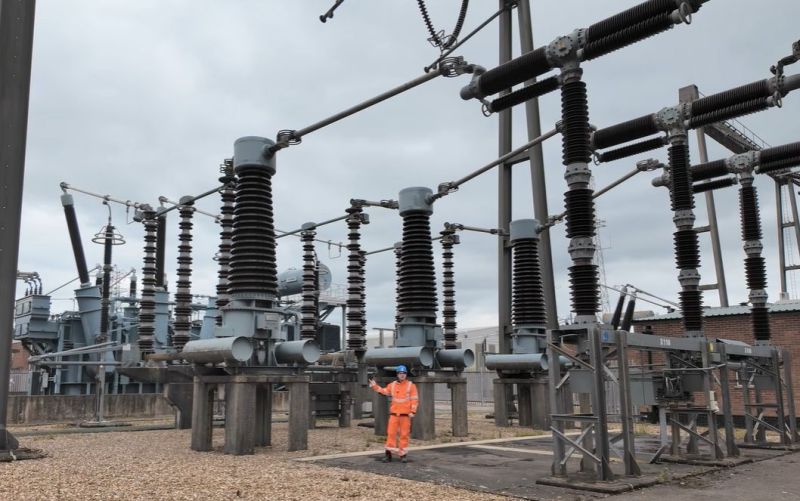
Being able to monitor voltages and currents is essential for many applications, with the national electrical grid being no exception. The obvious complication here is that the voltages and currents are massively higher than for those other applications, making safely monitoring these somewhat of an engineering challenge. The used systems for current monitoring are detailed by [Jordan Taylor], also known as [The Electric Brit], in an explainer of grid-level current transformers (CTs) and associated elements that help to provide galvanic isolation for safe current measurements.
Even if the basic principles remain the same, when you’re dealing with currents of 5 kA and more, the associated clearances and penalties for getting a detail wrong increasing correspondingly. The CTs help to implement over-current protection (OCP), over-voltage protection (OVP) as well as differential protection, which is useful to detect leakage and shorts, which could also happen inside the CT if the windings become damaged.
Any such failure condition can trigger a circuit breaker to be tripped, or other corrective measures to be taken. Incidentally this is also how it can be detected when someone is tapping off power in an illicit manner. As with all transformers they’re never perfect due to issues like core saturation, and thus performing accurate measurements and picking the right type of transformer is an art in itself, as explained in the video.
Ultimately CTs and the associated equipment are what makes an AC power grid responsive to any changes and with it into the reliable foundation of modern-day society.











So how can a CT detect fraud use? If I draw 1kWh without a meter from the grid, and my neighbor draws 500Wh with a meter, and that CT can measure this accuratly enough, maybe. But if both meters are Ferraris meters, how does this work? Asking for a friend.
Well if you draw 1kWh from the grid in one second the electricity company is going to know as it will look like a short circuit.
I guess this article refers to customers that don’t get billed by the kWh but instead pay a flat fee for average load and a surcharge for exceeding an allowed peak load. Heavy industries like aluminium smelting and steel mills fall in this category. Of course such customers want to stretch the contracts a bit and power companies want to catch that.
I think two things have been conflated in the article. Jordan is a transmission engineer and what he will see in his day job are basically protection CTs and High accuracy metering.
Protection CTs are designed to be linear to many times load currently (typically 20x) but to a lower accuracy. These feed into protection relays which then decide whether there is a fault scenario. There are several ways of doing this. High accuracy (HAM) CTs as the name suggests are part of the metering between the transmission network and other users. This would typically be distribution companies and generation or major consumers.
The illegal abstraction reference is very distribution focussed. There are two main types. Whole current, typical in domestic properties where the metering can handle line voltage and load current. Typically 100A. CT metering is then used where the current is higher. 100/5 CTs for example would allow the same 100A meter to measure up to 2000A. It is seldom on its own able to detect illegal abstraction.
Relay and meter tech and an electrician here. We would never use a 100a meter (self-contained) to meter 2000amps with a ct. We’d use an instrument rated meter which is generally a class 20 meter. If we want to meter a 2000amp load we’d do it with a 2000:5 CT on a CL20 meter. At our utility we have a few 100a meters left over from a long time ago, but the vast majority are class 200 meters( 200a), or class 320 meters 320 amp self-contained meters (CL200 or CL320). Any load over 320 amps single phase, or 200amps 3 phase becomes an instrument rated meter install with CTs, and any service voltage over 480 becomes an install with a CT and a PT.
Weird side note, some freight train signaling or monitoring services take a 480v single phase 2 wire service, those get a CL100 480v meter.
Electrical engineer here. One note is that CTs will do over current and differential protection, but they won’t work for over voltage protection. You’ll be using PTs for that.
Added Emporia Vue 2 CT info 5/29/23 T3
Here is some information I have discovered on CTs that might be of interest
to PV folks.
There are several good references on the web that can be consulted for more details.
Several interesting and important features of a true current transformer.
The secondary winding looks like a high impedance when no primary current is flowing.
All CT devices that need to monitor a primary current are all wired with the primary sides
in series so each sees the same current flow. Likewise, all measurement circuits
(Sensing or A/D converter) on the secondary side need to be wired in series so
all see the same current.
If the secondary of a true,current output, CT, is left open when there is primary current
very high voltages can result as the secondary tries to push the correct current thru the open
wires.
That means if the output of true current output CT is not used it needs to
be shorted.
To avoid these problems many CTs have internal terminating resistors so they
are voltage output rather that current output devices. They can be shorted
or left open when not in use.
The way these two styles are used is very different.
Loads on a true, current output, CT should be very low resistances and
should be wired in series.
Loads on a voltage, self terminated, CT should have high a resistance as
practical and be wired in parallel so they don’t load the resistor in the CT.
Notice that the typical industrial or electric system CT usually has a
5A secondary and will typically only put out a few VA or Watts.
Interesting things happen when you try to parallel CTs.
If you parallel true Current Output CTs the secondary current is
the vector sum of the two currents.
If you parallel voltage CTs the Volts/Amp rating drops due to the
parallel combination of the two terminating resistors in the CTs.
To protect Current CTs some have internal, or require external
“CT Savers” These are typically diodes that conduct and limit
the secondary voltage to a safe level.
Consider a typical 5A 5VA CT secondary. IF the device is not used
for overload sensing and breaker tripping the most the voltage should
be at full load is 1V. So, a full wave diode bridge with the
AC terminals in parallel with the CT output and one additional diode
with Anode on bridge plus and the Cathode on bridge minus effectively
puts 3 diode drops in series in each direction across the output
and limits the voltage to about 2V which should be safe for the CT.
NOTE: This is not a solution for a CT in protection circuit. That secondary current can
be many times nameplate during a fault so the circuit protective
devices can pick up and clear the circuit.
Enphase CT-200
Some basic measurements on the Enphase CT-200 split CTs appears to
reveal the following.
They are 2400:1 CTs and the Envoy inputs appear to be about 2.4ohms.
That makes the Enovy about 1mV per primary Amp.
The seem to parallel like true current CTs.
In testing, paralleling
the outputs of two devices while leaving one device with no current
resulted in no change in output as measured from just the active CT.
In phase currents in the two devices added as would be expected for a current output CT
i.e. 50A in a single CT produced about 21mA in the secondary.
Paralleling a second CT with no primary current did not change the reading.
50A in each of the two parallelled CTs (currents inphase) resulted in about 42mA.
Enporia Vue 2 CT
Spec says the 200A and 50A CTs are 0.333V for full output
One 50A CT showed a 20ohm resistance when not connected.
Would imply 3000:1 CT 16.6mA full scale. (Not confirmed)
Ifixit shows a 5 ohm internal terminator for the 200A CT
CT Testing:
A common way to test is a variac and supplying power to the 120V side of
a 120 to 6 or 12V transformer capable of 5 to 10A. Connect the secondary
thru the primary (window) of the CT. and thru a reference Ammeter
and back to the other secondary winding. Basically you have shorted the
secondary. Turn up the Variac slowly until you get the reference current
you desire. Adding a small, high power, resistor in the series string
makes the adjustment of the Variac less touchy.
If you need more current for testing a window style primary just wrap
turns thru the window. 20 turns thru the window turns 5A reference
current into 100A to the device.
Good luck, and be careful!
WB9VXY