
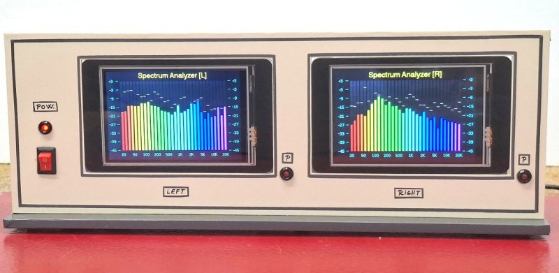
A slick spectrum analyzer used to be the kind of thing that would have been tricky to include in a DIY project, but as [Mirko “mircemk” Pavleski] demonstrates, a modern microcontroller like the ESP32 can handle the task with nothing more than a display panel and a few passives.
 This particular example is built around the CrowPanel 3.5, which combines the powerful microcontroller with a 480×320 touch screen LCD. But there’s nothing inherently special about the CrowPanel, and you could get similar results with whatever display you might have kicking around the parts bin — albeit potentially with some code changes to account for the different hardware.
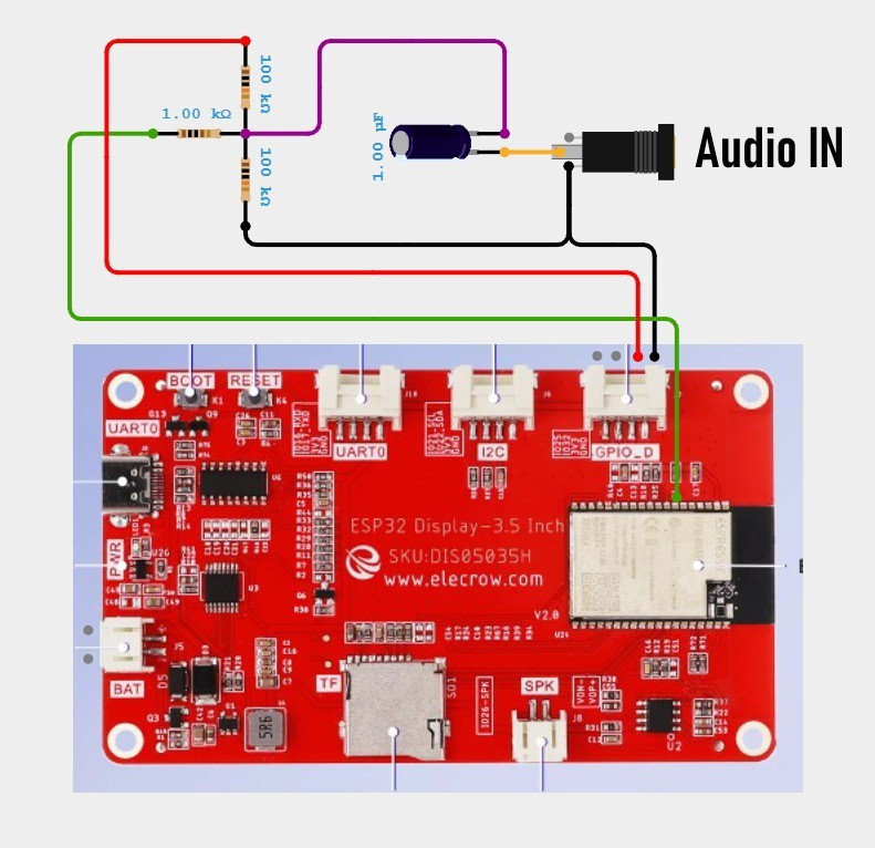
Beyond the microcontroller and the display, all you need to recreate what [mircemk] has done here is a handful of passives to tame the incoming analog audio signal so it can be piped into one of the analog-to-digital converter (ADC) pins on the MCU.
This project is fairly simple, but if you’re looking for something a little more advanced from [mircemk], don’t worry. The more daring home players can try their hand at recreating this high-voltage X-ray machine made from an old TV vacuum tube.












Really nicely done, Mirko! Great presentation…
I do have a question: based on your schematic, I cannot make out how you sample the L and R signals separately. It looks like you are just sampling separate polarities from one channel.
Thanks!
Based on the Hackaday.io link, I think that each display only has one channel attached to it (L or R). So two displays per enclosure, each one driven by a separate channel.
Thanks for pointing that out, Daniel! I clearly overlooked that detail…
I tried to download the code from the hackaday.io site but both .txt files appear to be corrupt. Is there a GitHub repository for this or am I doing something stupid?
Ignore that. It was a Unicode conversion issue.
I have put the downloaded code into a Arduino “sketch” and have flashed (uploaded) to the Crow 3.5 ESP32 display. When I reset the display, I get absolutely nothing on the screen, not even a flicker. I have not hooked up the signal input circuit yet, but figured the display would at least show some sign of life. Also, the Crow 3.5 display they shipped me was v2.2 which states TFT_Miso is moved to Pin 33 and Touch_CS to Pin 12.
Got it figured out. Needed to edit the “TFT_eSPI” library files as follows:
Select (enable) “#include <User_Setups/Setup204_ESP32_TouchDown.h>” line in file ‘User_Setup_Select.h’
Then edit ‘Setup204_ESP32_TouchDown.h’ file with this pin configuration:
#define TFT_BL 27
#define TFT_BACKLIGHT_ON HIGH
#define TFT_MISO 33
#define TFT_MOSI 13
#define TFT_SCLK 14
#define TFT_CS 15
#define TFT_DC 2
//#define TFT_RST 4
#define TOUCH_CS 12
This is for ver 2.2 of Crow 3.5 display, if using ver 2.0 set MISO to 12 and TOUCH_CS to 33
Now on to hooking up the inputs . . .