

Raspberry Pi has just leaked information on the Pi Zero 3W. They did it by publishing a DeviceTree file that describes the hardware of the Pi Zero. This is how we know it has the BCM2711 (Pi 4 CPU), makes use of PCIe (maybe it’s even exposed!), has an onboard power button, an extra power LED, and an eMMC option. If I were to guess, this will be the first dual-sided Pi Zero board, and if I were to have hope, it finally has USB-C.
Don’t believe it? Go read the DeviceTree file for yourself — it’s exceptionally easy to read it between the lines. DeviceTree files tell the Linux kernel, or other OS kernels, what CPU to expect, what drivers to load, which interfaces are exposed on your board, and the devices connected to those interfaces. Sometimes a proper DeviceTree file is the only thing you need to make a modern Linux OS run on a neglected SBC you own.
There are DeviceTree files powering technology all around you. Your phone has one, so does your router, your ARM laptop, and not even to speak of your SBCs. Some DeviceTree files are evil, being merely a thin layer between the Linux kernel and proprietary drivers; you will find these in phones with CPUs made by evil corporations. Most DeviceTree files are simply there to do their job.
What To Know
DeviceTree files describe hardware like HTML describes elements of a website. They are not Turing complete, and sadly, you cannot run Doom on DeviceTree alone – unless you find one of those evil implementations, I suppose. A DeviceTree source file (extensions .dts, .dtsi) gets compiled into a binary file (.dtb, .dtbo) able to read by your kernel. It’s relatively easy to decompile it and change things even if you don’t have the source!
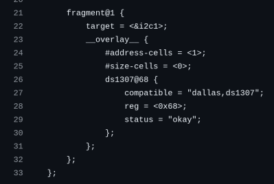
You can handle DeviceTree files pretty easily. Compile/decompile commands are dead simple and easy to find; the compiler is also a decompiler, a tiny utility that’s one sudo apt install device-tree-compiler away. For the Blepis PDA I’ve worked on, we have a script to compile a bunch of overlays for different displays that the Blepis can have, and it’s one of the most straightforward things ever.
There are a few types of DT files, like includes, base files, overlays. Includes (.dtsi) tend to hold information about the CPU, mostly the boring stuff you’d never touch, like some clock definitions. Base files describe the board fully, the kernel loads them and knows what to do with the board. Overlays are typically optional, they’re how you “add” features on top of the base DeviceTree, either describing extra devices or modifying the devices/interfaces already described. You’ve seen overlays mentioned in Raspberry Pi config.txt, without a doubt!
In fact, if you wanted to learn DeviceTree files by reading, you should check out the Raspberry Pi overlay source directory – could start from the README. There’s a ton in there and most of it is boring, but you will find gold if you look. By the way, you can also check out the base files in the broadcom/ DeviceTree base file directory to learn a lot about Raspberry Pi hardware as-is!
Learn By Numerous Examples
You will mostly want to write overlays, not base files. There isn’t much you need to learn to write overlays, because there are just so many places to learn from. In this intro, I will mostly describe the bare minimum you need to know to write an overlay that works. And 99% of time that will involve taking an existing overlay and slightly modifying it.
Here is a simple and exceptionally verbose LED overlay from Raspberry Pi, more comments than code, as if meant to be a training overlay! You describe an LED connected to a specific GPIO, its default state, its label, and even overrides so you can replace those parameters on the fly. Then, you can load the overlay with a single command line on a running system (this part is exclusive to Raspberry Pi), poke at the LED, turn it into heartbeat LED or a CPU activity signal, and load it permanently as a config.txt entry if you so wish. The file is nicely commented and explains basically everything.
Here’s an overlay that describes an I2C touchscreen connected to your Pi. Tweak the pin numbers to match, compile it, load it, and it should be automagically picked up by the kernel. Here is an overlay that disables WiFi on your Pi. Doesn’t this look super easy, just setting two variables to “disabled”? Here’s an overlay that describes an SPI Ethernet controller. It defines the pins used, and, it also takes care to set the specific SPI interface in use to “disabled”, so you can’t accidentally write into it from userspace.
At times Raspberry Pi overlays are too involved for their own good and hard to learn from, you can see just how many there are. Worry not, there are many other places to get examples from. The core Linux repository at large has no shortage, then there’s the Radxa overlay repository and Armbian’s everything-Rockchip repository, Armbian’s sunxi overlay (Allwinner) repository and its examples directory in particular… If you need some specific feature or device, someone already likely implemented it in an overlay and put it online. When just researching or even at your wits’ end, you can always search GitHub for .dts files containing your keywords of choice, too.
The Answers You Need
Languages like the DeviceTree one are uncommon, and DeviceTree overlays are obscure-ish, so here are things that you will rarely see explained to you but you absolutely should know, from my yet basic but somewhat experienced understanding if it.
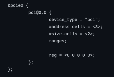 First off, DT overlay comments are C-style, with
// and /* */. Things like #size-cells and #address-cells, those are not comments, they are overlay metadata on how to read the <reg> property – keep them in, they’re important!
The & character in overlays is a pointer to things in the base file, so, the .dts (compiled into .dtb) of your board. Different CPU families and even different boards/CPUs have different naming conventions – for instance, GPIO pointers in Raspberry Pi .dts-es are named &gpio, on other boards they’re &pio, and sometimes pointers will refer to different controllers (&gpio1, &gpio2, etc.) if your CPU has too many GPIOs to handle them otherwise. When in doubt, open the base .dts to your board and make sure your pointer names match. When in further doubt, compare to other overlays for your board in places where you need clarification on which specific names to use.
Some overlays are more verbose, while other overlays are less verbose, and you can learn a lot comparing different ones. For instance, compare the Raspberry Pi ENC28J60 overlay to the Allwinner CPU ENC28J60 overlay. You can see that the Allwinner one doesn’t do SPI device disabling, and it doesn’t provide overrides – because you put overlay names into a single line in a uBoot config file, and Allwinner uBoot has nowhere to specify parameters, I presume? It also does the GPIO initialization block a tiny bit differently. To be safe, try and match the conventions of your target platform, generally not excluding/including sections because some other platform has them or omits them. Yes, I am essentially telling you to copy-paste more.
If you are overlaying hard enough and looking around, you will see that some overlays are written as if in short-form, omitting spells like __overlay__, fragment0 and so on. I genuinely don’t know the difference between these two styles, they certainly compile either way and appear to be equivalent ways of writing overlays, as this StackOverflow question also indicates. I tried to explore this further, but I can’t find any references to how these styles are even named, so for now I’m merely putting this on your radar to help you avoid surprises.
To the best of my knowledge, you can’t use #includes when doing overlays if you’re a mere mortal running a bare dtc command. You need a preprocessor for that, and your humble dtc commandline does not run one. Typically, you’ll encounter this by finding an overlay with #include directives online, trying to compile it locally, and getting errors. This means you have to un-define all #define-d parameters, replacing names with numbers wherever dtc complains.
For instance, a nice readable line like rockchip,pins = <4 RK_PA7 RK_FUNC_GPIO &pcfg_pull_up>; (an example from yet another ENC28J60 overlay) won’t compile on its own, you’d need to call a preprocessor, which is a whole undertaking. Instead, find numeric values of RK_PA7 and RK_FUNC_GPIO (they’re from the dt-bindings/pinctrl/rockchip.h include), and replace them, so your line looks like rockchip,pins = <4 7 0 &pcfg_pull_up>;. Ugly, but dtc won’t compile it for you until you do this. For your information, another common spot for include-d GPIO-related values in overlays is the dt-bindings/gpio/gpio.h include.
To the best of my knowledge, .dtbo files are compiled the same exact way as .dtb, and .dtbo is simply the file extension that the Raspberry Pi bootloader expects overlays to be named as. Other platforms don’t use .dtbo and instead use .dtb, again, from what I’ve seen. Also, if you’re using Armbian, use the armbian-add-overlay tool for all your overlay addition needs.
Raspberry Pi allows you to load overlays dynamically with the dtoverlay command, but as far as I understand, this is not implemented on other SBCs. So, when testing overlays on non-Pi targets, you’ll be stuck into a modify-reboot-test cycle, and if you mis-write an overlay real bad, it might just hang your system during boot so you’ll need to unplug the SD card and comment the overlay out to boot again. I suspect that when your system is on an eMMC drive, you won’t be able to do that either, so make sure you can recover in case of boot failure. This applies to any eMMC system, frankly, but you deserve a reminder because you’re messing with the boot process when hacking on overlays.
Ready To Dive In
Want to learn more? Here’s a ZephyrOS primer on DeviceTree overlays, a joy to read. Also, the DeviceTree spec is surprisingly readable as far as descriptive languages go, especially if you learn between the lines. It’s not a tutorial for sure, but if you need to get to the bottom of what specific lines in a devicetree file mean, there might not be a better fallback.
As last advice, be careful using LLMs for generating DeviceTree, especially if you don’t have sufficient LLM experience to know which one will work better for it. Sadly, accidentally having stumbled on some AI-generated DeviceTree “tutorials”, I found that they will outright hallucinate overlay properties at times; looks like for now, there’s no substitute for careful reading.
I’m currently hacking away at a DT overlay template, aiming to make a generator adapting the same overlay to tons of different SBCs at once – certainly, I will have something to tell in the next installment, even if I’m not exactly sure what it would be about. What about you? What aspects of DeviceTree, overlays or not, would you like to see covered next?








Please be kind and respectful to help make the comments section excellent. (Comment Policy)