
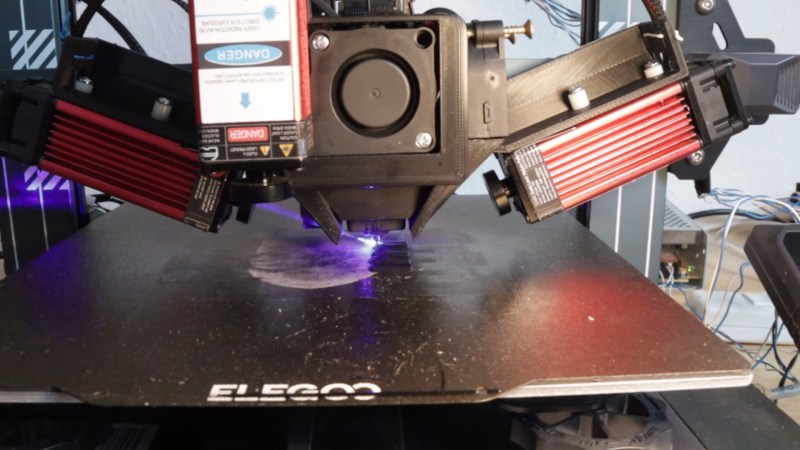
If there’s one defining factor about 3D printing you have to account for when you’re making a design, it’s probably layer adhesion. Sure, there are a lot of factors to consider, but having the z-axis of your part dramatically weaker than x- and y- is a pretty big deal in a whole lot of applications. [I Changed a thing] changed a thing to fix that — namely, he changed his 3D printer by strapping a couple of lasers to it. That’s the kind of hack we like to see!
What the lasers are doing is a very simple idea: they’re pre-melting the last-laid-down-layer just under the nozzle so that molten plastic is meeting molten plastic to create a much stronger joint than you get when you extrude onto an already-cold layer. The second layer keeps the hotspot warmer longer, which also helps the bond. The resulting parts are not purely isotropic, but he’s getting breaking strain along the z-axis of ABS that’s up to 94% of what he’s measuring in the x direction, while PLA still rates at 77.9%. That’s compared to 60% and 41%, for un-lasered samples, respectively. If you watch the video, you’ll get all the details for the printing process and can see more test data.
These lasers look like a game-changer, but their mass might slow down the fast coreXY printers that are so popular these days. If you don’t want to slow down, remember that changing your layer patterns can boost a print’s strength on its own.
Thanks to [Josh Pensel] for the tip!








I would like to see a test of these strengths vs. just using a heated chamber.
If there are lasers like this the machine will need to be fully enclosed (and likely ventilated). So if the enclosure is required anyways…might as well verify if you even need the lasers.
When I tested enclosures I was planning to have heaters/fans for the chamber temp but I realized pretty quickly that the heated bed gets the chamber to temp very quickly. It becomes an issue of needing to remove heat instead of adding it (at least in my tests).
Aside from that…the idea of heating the layer with a laser (or hotair) has been kicked around quite a bit in the reprap community for years…good to see someone getting around to testing it.
Gonna need to be a pretty hot heated chamber if it causes everything inside to glass transition. Also you don’t want the entire print to glass transition, it’ll become all rubbery and warp-y. You just want the area where molten PLA is about to go down to be in that state.
It doesn’t really need to do that – just keep everything hot enough that the newly laid down filament is now hot enough with enough thermal mass to remelt the still warm of the previous layers more for closer to isotropic plastic. (maybe even very warm with a fast printer and warm air the previous layer can still be too hot to print on without setting minimum layer times)
Inject particles?
https://phys.org/news/2026-08-particles-stable-glasses-stronger-catastrophic.html
Go from lost wax to lost print…
if the laser is properly scaled it would cause no more fume issue than the hotend. You dont want the laser to vaporize material, just warm it to the glass transition temperature.
a standard heated build chamber alone does improve layer adhesion significantly, but really just for plastics like ABS that have a high softening temperature, not for things like PLA. CNC Kitchen has a blog post with quantified measurements from a few years ago, and there are also a few scientific papers you can find demonstrating a huge improvement for specific materials like PEEK.
Compared to CNC kitchen’s result, this laser technique appears to be much more effective than a heated chamber for both ABS and PLA.
One caveat is that the hobbyist heated chambers aren’t actually run that hot, so it’s possible that the strength improvement for ABS is just from higher temperatures rather than technique. But the same can’t be said for PLA.
And running a hotter chamber has its own problems – the closer you get your heated chamber to the softening or glass transition temperature of your plastic, the harder it will be to avoid sagging, dimensional instability, and other print issues.
Regarding the issue with their mass, maybe putting the laser module away and putting a fiber as a guide-light between it and the nozzle to carry the light?
Are fibers good for cutting/melting lasers? I realize I’ve never seen that application before
Definitely- they can handle quite a lot of energy thru them, and might also be a way to get the laser output closer to the print head. They are made of glass, and can handle decently high temps (up to 300C with the right coating).
A fiber alone wouldnt get the job done. Lasers diverge from a raw fiber. Youd need to couple the fiber to a lens set.
For this application probably not – as long as the fibre exit is close enough to the nozzle that energy is being delivered in the right ballpark no matter how diverging out of the fibre, the goal isn’t to cut a neat pattern etc just to get the older layer warm enough to bond with – if anything the wider spot is probably what you want in this case, so a lens is only required if the mechanical packing or practical servicing (nozzle changes etc) force a too distant position.
@foldione without a lens youll need to use a much more powerful laser than with a lens.
Less concentrated power is actually a good thing in this case, where all you actually want is mild spot heating.
Not at all – as you actually want that pretty wide area to be impacted by the laser in this application, so the divergent spot size without a lensing setup could be exactly that area you actually want to heat if your fibre exit is close enough!
In which case the laser power you need is defined only by how that wavelength interacts with the plastic in question and how much extra kick you want to give it to get that isotropic behaviour.
The lens is only a value add if the fibre of the laser has to be for other reasons far enough from the nozzle that the divergence is significantly larger than desired heating zone.
Coupling it to a spherical lens to give a properly “fanned” distribution of energy to pre-heat the substrate before the next layer hits seems like a good place to start – the lenses we use for another application to build a rectangular beam are tiny and don’t weigh much so the whole arrangement wouldn’t add a lot of motion resistance (inertia and fiber flexing).
Maybe using some 45-degree mirrors and a stationary laser? I think Epilog uses something similar for a lightweight effector head and a large gas laser for cutting. Might be applicable here even when using a semiconductor laser like what they’re doing in the video, considering the CoreXY already has the axis separation one would need.
I absolutely agree. A static laser, a few angled mirrors, and a focusing lens would be a great approach for CoreXY.
Yes, this is essentially how Epilog does it (and nearly all other CO2 laser engravers do the same). The engraving head is essentially just a 45 degree mirror and focusing lens on the x-axis rail.
A lot of semiconductor diode laser engravers use mirrors and lenses now too. If you’ve got more than a watt or two of power, there will already be jobs where hauling the whole laser around is just going to slow you down.
In fact, most fiber laser engravers also steer their beam with mirrors and lenses, despite the laser itself being generated directly within a fiber. It’s just faster, simpler, and more robust.
(Many of them use galvo-steered mirrors, which is a slightly different approach, but the point is they still use mirrors and lenses, not fiber)
Now, you could run the laser directly to the extruder head through fiber, as other commenters have suggested, but I think they’re underestimating just how fragile, fiddly, and expensive it is to use fiber to deliver a laser in this application when mirrors will work just fine.
I wonder if a micro hot air nozzle could work this way. I’m thinking something like a metal syringe needle with hot air flowing through it.
That’s probably a great idea. The nozzle shouldn’t be a syringe.
It should be a ring with tiny holes at one face and a hot air air inlet on the other. The ring will be mounted such that the hot end of the 3d printer is at the center of the ring.
That would create an atmosphere of heat very close and around the nozzle just like the person wanted to do with lasers, but this being a ring will work for all movement directions.
Will need some tuning as the part cooling fans are working against this.
Perhaps even included in the extrusion nozzle. I wonder if the heater for the extrusion nozzle could be made to heat both the filament and the air jet.
I just tilt the model before slicing.
a tilted model has the same structural weakness caused by the weak bond between layers, its just on an angled plane.
If you angle it properly there’s little issue, certainly not been a problem for the automotive stuff I’ve done.
The automotive stuff youve done likely hasnt been subjected to any real loads. Angling just angles the layer lines. It doesnt make the part any stronger.
That depends entirely on the angle of the stress. The whole topic is about how one axis is weaker than the other two. Slicing at an angle can increase mechanical strength if it makes the layer lines perpendicular to the stress.
@douyarou Sure you can orient the part so the weakness is in the least stressed direction. BUT its still a weak flawed part thats only barely performing. But since 90% of the crap people poop out of FDM machines is nonfunctional knick knacks who cares.
This is not the way to do it, adding all that mass, better to have a fiber laser and bring the light to the target area via optical fiber/s traveling along the same path as the filament feed.
I’d like to see a tiny print put in an oyster to get a bit of nacre on it.
If you must slow down printing speed dramaticly because you’re hanging two heavy laser modules on you printing carriage you might as well just at the slow speed and raise your nozzle temperature a bit so the new layers melts the previous layer.
Same result and cheaper
The laser shouldn’t be attached to the extruder, just use a glass fibre near the nozzle. Advantage of the laser is that the locality of the heating is more accurate, increasing the nozzle heat melts everything in a relatively large radius.
A diode laser through a fiber solves the mass/CoreXY problem, but doesn’t change the physics. Common 450nm blue hobby engravers couple poorly with anything that isn’t carbon black. NIR diodes at 808-980nm give better penetration but are still weakly still weakly absorbed by unpigmented plastic, and wavelength varies module to module. Either way, absorption efficiency — how much of the laser’s power turns into surface heat vs. passing through — is going to depend heavily on filament color/pigment.
I think this is a very interesting idea. Some thoughts…
I’d like to see this tried printing a piece that is large and flat in the X and Y. Maybe a 30x30x3 cuboid.
I tried turning on ironing for all surfaces. This causes it to iron not just the top surface but also the bottom surface as it lays down the shell on the build plate. I found this causes parts that are wide and flat in the X and Y to warp badly and fail. It’s just too much localized uneven heating across the part. I wonder if this would be the same with the lasers.
It would be interesting to get an air quality meter and compare emissions with and without the lasers.
It would also be interesting to compare not just the layer adhesion but also the strength perpendicular to the layers. Is the second (and third) heating breaking down the plastic weakening it that way? (might still be worth it if it increases layer adhesion but good to know)
I am very skeptical about the utility of the trailing laser. It’s just heating the top layer where it was just printed, so… right where it is going to be the longest time before it is printed on top of. I guess it might still retain some of that heat for a very small part. But if the nozzle isn’t coming back there for a while that heat may be dissipated by then anyway. What was the point? I fear it might just be an extra heating cycle further breaking down the plastic with little gain.
That said, you would still want to have two lasers because the head can change direction. Unless you want to code a slicer that only extrudes in one direction.. which sounds like a terrible idea. But.. I am thinking the lasers could be cycled on and off via the printer’s firmware so only the leading laser fires at any time, not the trailing one. Unless… they take time to warm up. That would kill my plan.
I am also skeptical of the idea that he tried “annealing” the part with the laser. My understanding of “annealing” is that there is tension inside the structure of the part due to the fact that during printing there is always an uneven temperature, it’s melted right at the spot it’s printing and cooling everywhere else. “Annealing” heats the whole part uniformly, let’s that tension work itself out then cools it uniformly. The laser is just another point source of heat flying across creating tension again. I am not surprised at all that this was not beneficial.
One last thing but not so easy to accomplish.. it would be great to see this combined with non-planar printing.
Sorry, make that bigger. How about a 150x150x3mm cuboid.
“If there’s one defining factor about 3D printing you have to account for when you’re making a design, it’s probably layer adhesion.” NO! If you have to pick just one, the one defining factor is printability. Overhangs, towers, dimensional tolerance.
“having the z-axis of your part dramatically weaker than x- and y- is a pretty big deal in a whole lot of applications.” If your layer adhesion is this poor you are using the wrong filament or the wrong temperature / fan settings.
Layer adhesion is almost completely a non-issue. Meditating on it will not solve the problems you’re having. Brittleness, creep, heat deformation, PRINTABILITY are all ten or a hundred times bigger problems than layer adhesion.
I hear sometimes about how ABS layer adhesion is an order of magnitude worse than PLA or PETG so for some people layer adhesion does matter. But first off, you shouldn’t be using ABS. And also, ABS’s printability isuses are also an order of magnitude worse than PLA or PETG.
You shouldn’t print ABS???
I used to print ABS almost exclusively. I didn’t and don’t like PLA because parts that I printed to go outside turned lost their shapes in the hot sun.
I didn’t print PETG back then because I didn’t have a full-metal hotend and the recommended print temps for PETG were too close to where the nylon insert turns into a toxic gas.
Since I got my first full-metal hotend I have loved PETG for it’s printability while still being good enough to survive outdoors or even in my hot car. I don’t use ABS much anymore but I still think telling someone NEVER to use it is bad advice!
ABS still has some advantages over PETG
• It takes sanding much better.
• It takes glue and paint better than PETG
• You can even carve it if you really want to.
• It can survive even more heat than PETG. So.. if you live closer to the equator than I that might matter.
• Even better than glue.. you can chemically weld it using acetone. I always loved that about ABS! Complex part with overhangs no matter which side is up? Split it in two, Solvent weld the halves together!
• I haven’t tried it but then there is always acetone vapor smoothing… I remember seeing pictures that looked pretty good!
I guess there are other filament types I haven’t tried. Nylon maybe? Most are expensive, require extra-hot hotends or both.
Some tips for printing with ABS…
• ABS goo! Take some scrap and dissolve it in acetone. Spread a thin layer of that on your glass build plate. It will stick to the plate a lot better and warp less.
• Cover your printer! I have a tent for mine now. I used to put a large box over it. I even had a little heater that was meant for defrosting a car window that I would sometimes stick in the box with the printer to heat the air.
ABS goo can be too good – better to put down a layer of it on kapton tape. You might get the odd wrinkle/bubble showing up in that bottom layer if you didn’t get the tape application clean enough but you will never break the build plate trying to get the part off. The tape is also usually good for many prints.
I do agree though I still print almost everything in ABS as it isn’t that hard to print once you figure out the heated bed/chamber and feeds/speeds and the end results are great mechanically while the easy solvent weld makes complex parts much easier to print. It is more warp prone than most, but you can tame that, and once you do figure it out the prints are reliably good.