
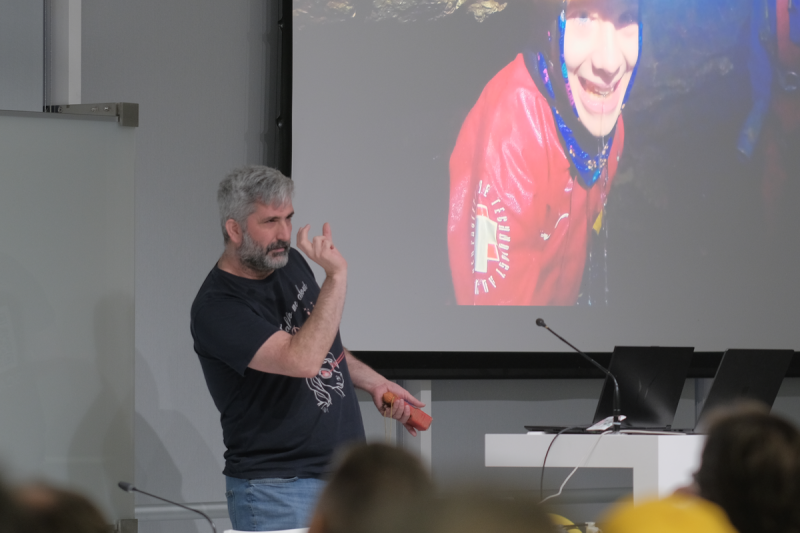
These days open source is everywhere, and frankly, we couldn’t be happier about it. But even with as prevalent as open software and hardware has become, we still occasionally hear about a project that takes the concept somewhere unexpected. Which is precisely why we were so eager to hear more about the fascinating work [Phil Underwood] has been doing.
In his talk Open Source Caving: 20 Years of Making Cave Mapping Tools at Hackaday Europe 2026, [Phil] takes us through a series of progressively more advanced open hardware devices that he’s designed to increase the speed and accuracy of underground mapping efforts. Along the way, he’s learned a number of valuable lessons about designing hardware that’s robust enough to handle the uniquely challenging environment underground while still being accessible enough for a hobbyist to build and use.
Improving on the Old School
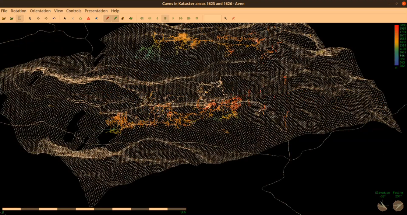
It’s not much of a stretch to assume that most Hackaday readers haven’t spent a lot of time crawling through underground passages, and as such, may not be immediately aware of how one begins to map a cave in the first place. Helpfully [Phil] starts off his talk by explaining the traditional process — which generally involves a compass, an inclinometer, a tape measure, and plenty of intricate notes.
Once you’ve collected all that data and successfully returned to the surface with it, you can plug it into software and create a three dimensional map of the cave. Sprinkle in some surface topography, and you’ve got a pretty slick overview of whats above and below ground.
Like so many other cavers, [Phil] wanted a way to make that first half of the process a bit less tedious. He imagined an electronic device that could take at least some of the necessary measurements for him, but was limited by the technology and at-home production capabilities available to hobbyists in the early 2000s. There was also the cave environment to contend with: any piece of equipment used in a cave not only needs to be able to handle the dusty and cramped conditions, but must be reasonable shock resistant. If that wasn’t tricky enough, there’s also a non-zero chance that it will need to spend some amount of time underwater.
Incremental Improvements
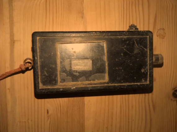
The first-generation of [Phil]’s surveying device. Undaunted, [Phil] put his first electronic caving aid together in 2008. Inside the off-the-shelf Radio Shack enclosure was an 8-bit PIC18LF2550, a dot-matrix display, an accelerometer, and a magnetometer. The data from the two sensors could be used to determine the heading and angle that the device was being held at, and while it still required the operator to manually take a distance measurement along that vector, having two-thirds of the information already computed saved considerable time and effort during surveys.
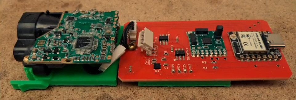
Thanks to the the increased computational capabilities offered by the modern MCU, more of the necessary calculations could be done on the device itself, which further sped up the surveying process. But [Phil] notes that the data from the laser module wasn’t always reliable, and keeping the more complex device protected from the elements introduced new challenges.
Now evolving at a faster clip, by 2023 [Phil] had improved on the design with a better integrated 3D printed case, custom silicone buttons, and a more polished user interface. At this point, he also switched over to writing the device’s firmware in CircuitPython. The lower bar of entry compared to C seemed to better resonate with those in the community, and consequently [Phil] started seeing more code contributions from outsiders.
New Dimension, New Challenges
By this point [Phil] had a pretty solid handheld device to assist in performing cave surveys, but the end result was ultimately the same as if the measurements had been taken manually. Each successive generation of the hardware made the process of gathering spatial data faster and less cumbersome, but didn’t meaningfully improve the final product.
Creating higher fidelity maps would require more data and the computational power to churn through it, which is why the latest generation of [Phil]’s hardware utilizes a Raspberry Pi 5 Compute Module and a pair of low-light cameras to perform photogrammetry. When combined with the heading and angle data, this produces a textured 3D model of the inside of the cave with minimal manual effort on the part of the user.
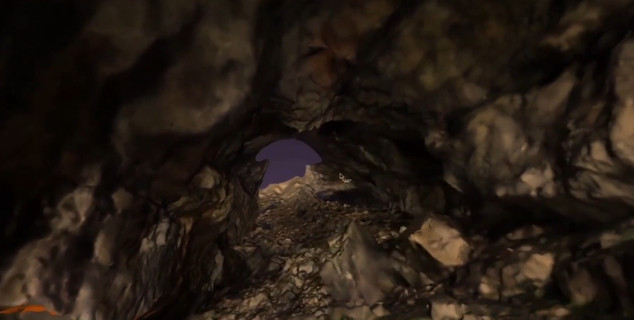
While this latest generation of hardware is undeniably more capable than what came before it, there’s an argument to be made that it also takes a step backwards in some respects. The cameras represent a physical weak point, and [Phil] says he’s still working on an approach to more adequately handle the increased power requirements of the Pi 5 Compute Module compared to the microcontrollers used in his earlier devices. But just as with the rest of the problems faced over the last two decades, these issues will likely be resolved in time as well.
In the end, this incremental approach to hardware development may be the most valuable lesson to take away from [Phil Underwood]’s talk. It’s a safe bet that the vast majority of those who view this presentation will never find themselves exploring an underground cave system, much less mapping one. But that doesn’t mean they can’t learn from his practical and methodical approach to building the right tool for the job.












Back in the 1970’s, when I did cave mapping, we used stone knives and bear skins (a Mr Spock quote). Actually, we used the Brunton Pocket Transit.
I also remember someone gave a presentation about communcating between the surface and the cave. They determined that frequencies around 300-500 kHz worked best. The drawback was that you had to trail a long wire behind you for an antenna.
As an aside, the wireless air gauge use on SCUBA gear transmits around 38 kHz. This seems to work best under water. As I understand it, the Navy uses similar frequencies to send messages to submarines.
What’s with all the hoopola over open source hardware- when it’s the work of one guy?
You are not stuck when the guy dies/loses interest or the base commercial instrument the caving version uses is discontinued (as has happened with a previous proprietary cave-surveying device).
And in fact, as the article says, there have recently been spin-off projects because the design is open. The DiscoX is a derivative of Phil’s SAP6 with better waterproofing and software changes.
The related area of cave communications is really suffering at the moment as the primary device (cavelink) is proprietary, but the producer is unwell, and no longer manufacturing, and none of us can fix or improve our £1000 devices.
Open designs are just better, especially in niche areas like this.
I didn’t know about Cavelink, but it sounds like a good target for a hack. What does Cavelink use for an antenna, a large coil?
Another option – I would think that with all the LORA and Meshtastic projects (also low bandwidth), someone could use some of that knowledge to make a VLF radio that does text. This is Hackaday, after all.
From the ARRL website:
Another LF band does exist in the US. A lot of “lowfer” (Low Frequency Experimental Radio) activity occurs in the 160 to 190-kHz region–the so-called 1750-meter band, authorized under Part 15 of the FCC regulations. You don’t need a license to operate on 1750 meters, but there are severe legal restrictions on what you can put on the air there. For starters, you can’t run more than 1 W input to the transmitter’s final stage, and the entire length of the transmission line and antenna combined cannot exceed 15 meters (approximately 50 feet). That’s not much antenna for a band where a half-wavelength antenna would be more than one-half mile long! Hams that operate on 1750 meters use just their call sign suffix as an ID as the FCC frowns on using call signs there.
Right now, a few hundred experimenters occupy the band in the US, and several of them have set up CW beacons on 1750 meters (many between 180 and 190 kHz), so you might take a listen if you have a receiver that tunes those nether regions. A lot of equipment for the band is homebrew, but commercial equipment is becoming more available.
I don’t know if 1 W is enough, or another frequency range is better, but you could apply for an experimental license. That’s what those guys did with the system I mentioned above (it was voice). They were Amaterurs, but I don’t think that is required.
Cavelink uses a long wire with plates+foil to couple to the ground/rock at the ends. The longer the better, especially for serious depth. e.g for 600m down in the Berger the supplied 50m antenna is useless, but the 500m one in the cave works great.
There are other designs for digital cave radio (e.g. system Nicola), but it’s a hard thing to make work well. Cavelink puts 20-40W into the ground (at ~140V) for deep comms. A 1W radio will not get you very far at all. The power is going into the ground so normal broadcast power restrictions do not apply. It uses 20-100kWh. 42kWh is a popular frequency.
Huh?
If you want to build on or study the existing work, you can, and you’re encouraged to.