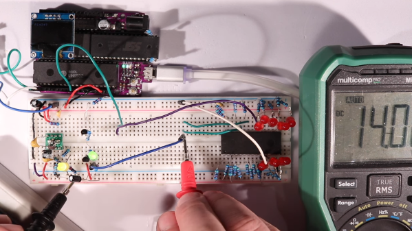
When is 14 volts not actually 14 volts? Given [Anders Nielsen]’s recent struggles with erasing an old-school EEPROM, it’s when you really need it that things tend to go pear-shaped.
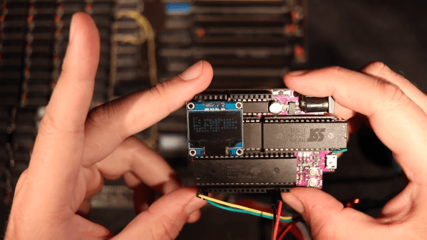
A little background is perhaps in order. [Anders] is working on a scratch-built programmer for ROMs to complement his 65uino project, which puts a complete 6502 computer into the footprint of an Arduino Uno. He wisely started the ROM programmer project at the beginning, which was to generate the correct voltages for programming. This turned out to be not as easy as you might think thanks to the solderless breadboard’s parasitic effects on the MIC2288 switching boost regulator he chose.
The video below is a continuation of the programmer build, which ends up being just as fraught as the first part. Being able to generate the programming voltages is one thing; getting them onto the right pins at the right time using nothing but the 5-volt GPIOs on a microcontroller is another. In true retro fashion, [Anders] tackled that problem with a pair of small-signal transistors, which seemed to work once the resistor values were sorted, at least when applying a 12-volt signal intended to show the ROM’s hard-coded manufacturer ID on the data bus.
But erasing the ROM, which requires 14 volts while the chip enable line is held high for 100 ms, proved a little trickier. Despite multiple tries, the ROM wouldn’t erase thanks to the 14-volt rail being dragged down to around 9 volts. [Anders] fixed that with a new base resistor on the driver, to increase the current and keep the voltage up where it needs to be. Just goes to show you that the data sheets don’t always tell the whole story.
We’ve been enjoying the unfolding story of this programmer, and we’re looking forward to the next installment.
Continue reading “Erasing EEPROMs Isn’t Always As Easy As It Seems”


