Ask Hackaday: What To Do With A Home Intercom System?

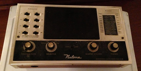
[Kyle] just moved into a new home, a 1970s abode that was very modern for its time. When the house was built, a home intercom system was installed. Of course this intercom system was eventually disconnected, but now [Kyle] would like to find a use for it.

The intercom system is a wonderful piece of engineering from the late 60s and early 70s. The base station has an FM radio, a mono input (for plugging in a turntable, we suppose), and a huge speaker. The satellite units – one for each room in the house – are much simpler with just a push to talk switch and a volume control. Yes, in classic minimalist style, the engineers for this intercom system used the speaker as a microphone.

[Kyle] would like to keep the wonderful plastic fantastic aesthetic of the intercom system, but he’s looking for something cool to do with this hardware.  This could be the beginnings of a very cool, very strange house-wide artificial intelligence build, kind of like a consumer version of HAL 9000. We’re interested in hearing what you’d do with [Kyle]’s hardware, so leave your ideas in the comments.

Ask Hackaday: We Might Have Some FPGAs To Hack

rear

[Chris] is an IT guy for a medical clinic up in Alaska, and until very recently the systems he monitored, fixed, and beat with a wrench included over 100 Pano Logic “Zero Client” thin clients. Pano Logic just went out of business and all support for these little boxes have been cut off, leaving [Chris] with a hundred or so very interesting pieces of hardware.

The idea behind these “zero clients” is the ideal of a thin client – take all the storage, processing, RAM, and other goodies and move them to a server. Pano Logic took this one step further than other thin clients, removing the CPU, memory, and basically everything you’d find in a thin client. What was left was a Spartan-6 FPGA, a few chips to drive the USB ports, a pair of HDMI chips, and a few DDR2 modules. Basically, [Chris] has about 150 FPGA dev boards just sitting in a storage room. The only thing that is needed is a bunch of software and an extreme amount of cleverness.

After opening one of these zero clients, [Chris] found a Spartan-6 FPGA right next to what he thinks is a 6-pin programming port. Along with the FPGA are a few other chips that would make any FPGA dev board a very neat tool:

We’re going to agree with [Chris] these Pano Logic zero clients show a lot of potential. If you’re up to the challenge of creating a very, very cheap FPGA dev board out of some discarded hardware, head on over to ebay or chat up your local IT guy.

Ask Hackaday: How Do You Give A Project Away?

lcr

A few weeks ago, we caught wind of a DIY version of ‘smart tweezers’ from [Kai]’s workbench that are able to measure SMD resistors, caps, and inductors. At that time, [Kai] hadn’t quite finished the software portion of his build, leaving him with a pile of parts and non-working PCBs. The code is finished now, meaning [Kai] has a very capable and very inexpensive version of LCR meter tweezers. He’d like to give back to the open source community and figure out a way to get his tweezers into the hands of makers the world over now. The only problem is he doesn’t know quite how to do that.

We’ve seen smart tweezers before, and they’re still available commercially for about $300. [Kai]’s version brings down the price significantly, so there is a market for these LCR tweezers. The problem, it seems, is getting these tweezers manufactured.

We’re assuming that soldering hundreds of thousand of SMD parts isn’t what [Kai] thinks is a good time; this leaves a Kickstarter as a non-starter, unless he can contract out the manufacturing. Seeed Studio might be a good place for [Kai] to sell his wares, but we’re wondering what Hackaday readers would do in [Kai]’s situation. Obviously he deserves to compensated for his work either through licensing or royalties, but as far as actual advice and recommendations we’re turning to Hackaday readers.

Ask Hackaday: Has Anyone Built A Radio Telescope?

[Michael] sent in a question regarding the latest advances in software defined radios available for $20 on eBay:

I’ve been looking in to SDR lately, mainly for the possibility of using it for incredibly cheap radio astronomy. So far all I’ve found are whispers. I’m 18 and have very little experience, but I figured you might be able to help me find a little more info.

This really brings me back, [Michael]. I saw Contact in the theater (surprisingly, a rare case when the book and movie are equals), and in my childish exuberance went out and listened to lightning on Jupiter. The financial difficulties of expanding my setup meant the experiments stopped there, but at least I knew amateur radio telescopy was possible.

The latest and greatest advance in software defined radio – namely, a $20 TV tuner dongle – brings something new to the table. Instead of the thousands of dollars in gear that was required in 1997 when I last looked into this, it’s possible to set up a  passable radio telescope for under $100.

I’ll leave it to the Hackaday commentors to fill [Michael] in on the details, but here’s my suggestion:

Optimize your setup for 1420 MHz. There are three reasons for this: firstly, very few things in the universe absorb radio waves at a frequency of 1420MHz; there’s a reason it’s so often used in radio astronomy. Secondly, most government agencies around the world ban (or at least don’t look too kindly upon) transmitting on 1420 MHz. This frequency has been somewhat protected for use by astronomers. Thirdly, most of the Realtek TV tuner dongles have a frequency range of 64 – 1700 MHz, so it’s possible to receive 1420 MHz with this minimal setup.

As far as antennas go, your best bet is probably going to be one of those old C-band parabolic antennas from the 80s. That will make your telescope highly directional and give it a huge amount of gain. There is the problem of having a 20-foot-wide eyesore in your back yard, however. Alternatively, you could use a smaller DirecTV satellite dish, but I’m not making any promises with that. It’ll work, but it’s too small for an optimal setup.

I’ll concede the floor to anyone who has additional information. If you’ve built a radio telescope, send it in and I’ll put it up.

Ask Hackaday: Troll Physics Super Deluxe Edition

Here’s a brain bender for you: YouTube user [Fredzislaw100] put up a video of six LEDs and six switches wired up in series. After soldering a resistor and 9V battery connector, the first switch turns on the first LED, the second switch turns on the second LED, and so on for the rest of the circuit.

We’ve seen this trick before from [Fredzislaw100], only this time he’s moved up from 3 LEDs to 6. In the reveal of the previous trick, [Fredzislaw] built two AC power supplies inside a nine volt battery connector; one high frequency and one low frequency. The low frequency AC line powers the first two LEDs with the help of diodes in the switches and LEDs. The high frequency AC line turns on the third LED with the help of an inductor inside an LED. Apparently [Fredzislaw] still has some soldering skills to show off; the circuit powering this trick is most likely the work of a soldering god.

From a close viewing, it looks like LEDs are wired up in pairs, i.e. LED 1 works the same as LED 2, LED 3 works the same as LED 4, etc. We’ll let Hackaday readers argue it out in the comments as to how this trick is possible.

Tip ‘o the hat to [Th0m4S] for sending this one in.

Ask Hackaday: Did You Catch The Grammys?

Although award shows aren’t necessarily our thing, [T. D.] sent in something that piqued our interest. His friends recently got back from the Grammy awards where they witnessed thousands of LED bracelets blinking in time to a performance by Coldplay. A little bit of YouTubing pulled up this video that demonstrates the effect (because that video will probably be taken down shortly, just pick something from this link).

[T.D.]’s friends brought one of these bracelets back with them and like a good Hackaday reader, he cracked it open. This is the precious board pic that [T.D.] sent in. We’re pretty confident that the IC is an ATMega48PA, but beyond that we’re not quite sure how these bracelets can, “light up and flash at precisely the right time” as [T.D.] puts it.

From what we saw on the Grammy broadcast, it’s possible these bracelets merely flashed whenever the user clapped their hands. A circuit that simple doesn’t require a microcontroller, so we’re left wondering what the heck is going on here. If you’ve got an idea of how these choreographed light display bracelets work, drop a note in the comments.

EDIT: Commentors have pointed out these wristbands are called ‘Xylobands.’ There’s a great video of these wristbands in action at the 2011 X Factor finale.

Ask Hackaday: Troll Physics Edition

[Martin] sent in two videos he found while cruising the tubes. The first video is a simple circuit with a resistor, three switches, and three LEDs. All the components are soldered together right in front of the camera. When a battery is connected, turning the first switch on makes the first LED light up. Turning the second switch on makes the second LED light up, and the same thing goes for the third switch and LED. Obviously we’re dealing with powers that are incomprehensible with even several cups of coffee.

The second video features the same resistor/switches/LEDs, this time in a parallel circuit. Turning on the first switch makes the first LED light up, and the second switch makes the second LED light up. Truly we are dealing with an expert in troll physics.

This is probably something really benign and uninteresting, but it sure is enough to wake up enough brain cells on a Monday morning. We’re not going to hypothesize, so check out the comments where we expect the correct answer to be.

Continue reading “Ask Hackaday: Troll Physics Edition”