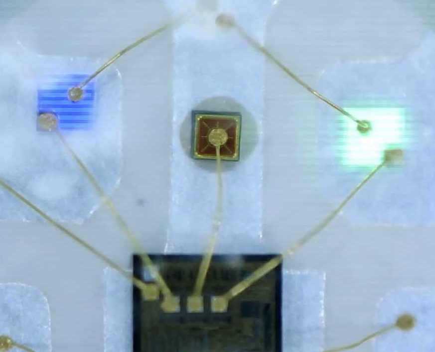
In firmware-land we usually refer to colors using RGB. This is intuitively pleasing with a little background on color theory and an understanding of how multicolor LEDs work. Most of the colorful LEDs we are use not actually a single diode. They are red, green, and blue diodes shoved together in tight quarters. (Though interestingly very high end LEDs use even more colors than that, but that’s a topic for another article.) When all three light up at once the emitted light munges together into a single color which your brain perceives. Appropriately the schematic symbol for an RGB LED without an onboard controller typically depicts three discrete LEDs all together. So it’s clear why representing an RGB LED in code as three individual values {R, G, B} makes sense. But binding our representation of color in firmware to the physical system we accidentally limit ourselves.

Last time we talked about color spaces, we learned about different ways to represent color spatially. The key insight was that these models called color spaces could be used to represent the same colors using different groups of values. And in fact that the grouped values themselves could be used to describe multidimensional spacial coordinates. But that post was missing the punchline. “So what if you can represent colors in a cylinder!” I hear you cry. “Why do I care?” Well, it turns out that using colorspace can make some common firmware tasks easier. Follow on to learn how!
Continue reading “Buttery Smooth Fades With The Power Of HSV”


