True or false? Your green laser pointer is more powerful than your red one. The answer is almost certainly false. They are, most likely, the same power, but your eye is far more sensitive to green, so it seems stronger. [Brandon Li] was thinking about how to best represent colors on computer screens and fell down the rabbit hole of what colors look like when arranged in a spectrum. Spoiler alert: almost all the images you see of the spectrum are incorrect in some way. The problem isn’t in our understanding of the physics, but more in the understanding of how humans perceive color.
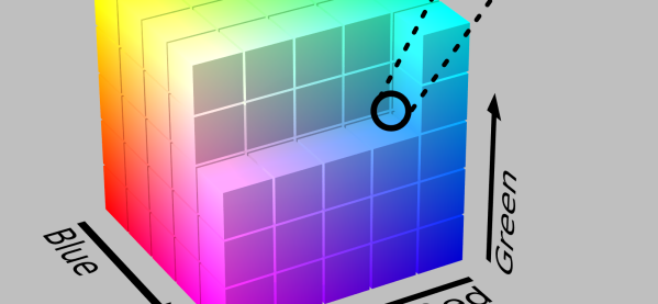
Perception may start with physics, but it also extends to the biology of your eye and the psychology of your brain. What follows is a lot of math that finally winds up with the CIE 1931 color space diagram and the CIE 2012 system.