How Many Commodores Does It Take To Crack A Nut?

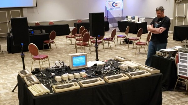
It’s brilliant enough when composers make use of the “2SID” technique to double the channels in a Commodore 64 with two sound chips, but even then some people like to kick things up a notch. Say, five times more. [David Youd], [David Knapp] and [Joeri van Haren] worked together to bring us just that, ten Commodore computers synchronously playing a beautiful rendition of the Dance of the Sugar Plum Fairy at this year’s Commodore Retro eXpo.

The feat is composed of nine Commodore 64 computers and one Commodore 128, all fitted with the SID chip. It is a notorious synthesizer chip for utilizing both analog and digital circuitry, making each and every one of its revisions unique to a trained ear, not to mention impossible to faithfully reproduce in emulation. The SID was designed by Bob Yannes at MOS Technology, who later went on to co-found Ensoniq with his experience in making digital synthesizers.

How this orchestra of retro computers came to be, including details on how everything is pieced together can be found on this slideshow prepared by the authors of the exhibition. It’s interesting to note that because of timing differences in each computer’s crystal clock and how only the start of the song is synchronized between them, they can’t play long music tracks accurately yet, but a 90-second piece works just fine for this demonstration.

These synthesizer chips are slowly going extinct since they’re no longer being manufactured, so if you need a new replacement solution, FPGAs can fill that SID-shaped hole in your heart. If you need the whole computer though, the newer Teensy 3.6 will do just fine emulating it all. Check out this beast of a display in action after the break. While we’re at it, this isn’t the only time multiple 8-bit computers have been combined as an orchestra, though these Commodores sound a lot better than a table full of ZX Spectrums.

Continue reading “How Many Commodores Does It Take To Crack A Nut?”

Anatomy Of A Power Outage: Explaining The August Outage Affecting 5% Of Britain

Without warning on an early August evening a significant proportion of the electricity grid in the UK went dark. It was still daylight so the disruption caused was not as large as it might have been, but it does highlight how we take a stable power grid for granted.

The story is a fascinating one of a 76-second chain of unexpected shutdown events in which individual systems reacted according to their programming, resulted in a partial grid load shedding — what we might refer to as a shutdown. [Mitch O’Neill] has provided an analysis of the official report which translates the timeline into easily accessible text.

It started with a lightning strike on a segment of the high-voltage National Grid, which triggered a transient surge and a consequent disconnect of about 500MW of small-scale generation such as solar farms. This in turn led to a large offshore wind farm deloading itself, and then a steam turbine at Little Barford power station. The grid responded by bringing emergency capacity online, presumably including the Dinorwig pumped-storage plant we visited back in 2017.

Perhaps the most interesting part followed is that the steam turbine was part of a combined cycle plant, processing the heat from a pair of gas turbine generators. As it came offline it caused the two gas turbines feeding it to experience high steam pressure, meaning that they too had to come offline. The grid had no further spare capacity at this point, and as its frequency dropped below a trigger point of 48.8 Hz an automatic deloading began, in effect a controlled shutdown of part of the grid to reduce load.

This is a hidden world that few outside the high-power generation and transmission industries will ever see, so it’s very much worth a read. It’s something we’ve touched on before with the South American grid shutdown back in June, and for entirely different reasons in 2018 when an international disagreement caused the entire European grid to slow down.

Header image: Little Barford combined-cycle power station against the sunset. Tony Foster, (CC BY-SA 2.0).

Fail Of The Week: Taking Apart A Tesla Battery

It takes a lot of energy to push a car-sized object a few hundred miles. Either a few gallons of gasoline or several thousand lithium batteries will get the job done. That’s certainly a lot of batteries, and a lot more potential to be unlocked for their use than hurling chunks of metal around on wheels. If you have an idea for how to better use those batteries for something else, that’s certainly an option, although it’s not always quite as easy as it seems.

In this video, [Kerry] at [EVEngineering] has acquired a Tesla Model 3 battery pack and begins to take it apart. Unlike other Tesla batteries, and even more unlike Leaf or Prius packs, the Model 3 battery is extremely difficult to work with. As a manufacturing cost savings measure, it seems that Tesla found out that gluing the individual cells together would be less expensive compared to other methods where the cells are more modular and serviceable. That means that to remove the individual cells without damaging them, several layers of glue and plastic have to be removed before you can start hammering the cells out with a PEX wedge and a hammer. This method tends to be extremely time consuming.

If you just happen to have a Model 3 battery lying around, [Kerry] notes that it is possible to reuse the cells if you have the time, but doesn’t recommend it unless you really need the energy density found in these 21700 cells. Apparently they are not easy to find outside of Model 3 packs, and either way, it seems as though using a battery from a Nissan Leaf might be a whole lot easier anyway.

Continue reading “Fail Of The Week: Taking Apart A Tesla Battery”

Reducing Drill Bit Wear The Cryogenic Way

There are a lot of ways that metals can be formed into various shapes. Forging, casting, and cutting are some methods of getting the metal in the correct shape. An oft-overlooked aspect of smithing (at least by non-smiths) is the effect of temperature on the final characteristics of the metal, such as strength, brittleness, and even color. A smith may dunk a freshly forged sword into a bucket of oil or water to make the metal harder, or a craftsman with a drill bit might treat it with an extremely cold temperature to keep it from wearing out as quickly.

Welcome to the world of cryogenic treatment. Unlike quenching, where a hot metal is quickly cooled to create a hard crystal structure in the metal, cryogenic treatment is done by cooling the metal off slowly, and then raising it back up to room temperature slowly as well. The two processes are related in that they both achieve a certain amount of crystal structure formation, but the extreme cold helps create even more of the structure than simply tempering and quenching it does. The crystal structure wears out much less quickly than untreated steel, therefore the bits last much longer.

[Applied Science] goes deep into the theory behind these temperature treatments on the steel, and the results speak for themselves. With the liquid nitrogen treatments the bits were easily able to drill double the number of holes on average. The experiment was single-blind too, so the subjectivity of the experimenter was limited. There’s plenty to learn about heat-treated metals as well, even if you don’t have a liquid nitrogen generator at home.

Thanks to [baldpower] for the tip!

Continue reading “Reducing Drill Bit Wear The Cryogenic Way”

Is Solar Right For You? Find Out!

Solar panels are revolutionizing the electric power industry, but not everyone is a good candidate for rooftop solar. Obviously people in extreme northern or sothern latitudes aren’t going to be making a ton of energy during the winter compared to people living closer to the equator, for example, but there are other factors at play that are more specific to each individual house. To find out if any one in particular will benefit from solar panels, [Jake] and [Ryan]’s solar intensity sensor will help you find out.

The long-term intensity tracker is equipped with a small solar panel and a data recording device, properly contained in a waterproof enclosure, and is intended to be placed in the exact location that a potential solar installation will be. Once it has finished gathering data, it will help determine if it makes economical sense to install panels given that the roof slope might not be ideal, landscaping may be in the way, or you live in a climate where it rains a lot in the summer during peak production times.

As we move into the future of cheap, reliable solar panels, projects like this will become more and more valuable. If you’re not convinced yet that photovoltaics are the way of the future, though, there are other ways of harnessing that free solar power.

Putting 3D Printed Speaker Drivers To The Test

Over the years, we’ve seen numerous projects that attempted to 3D print speaker enclosures that deliver not only a bit of custom flair, but hopefully halfway decent sound. Though as you’d probably expect, the drivers themselves are always standard run-of-the mill hardware mounted into the plastic enclosure. But given the research being conducted by [Paul Ellis], that might not be a safe assumption for much longer.

His quest to develop a full-range 3D speaker has taken him through several design revisions over the last two years, with each one being put through testing procedure that compared its frequency response to “real” speakers from manufacturers like Dayton and Bose. The project is very much ongoing, but a recently completed iteration of the driver design managed to exceed 80 dB at 1 W. In terms of audio quality, [Paul] reports they can hold their own against commercially available drivers. You can hear for yourself in the video after the break.

Ultimately, he hopes to be able to sell his 3D printed speakers in kit form to anyone who’s looking for the last word in bespoke audio hardware. The idea being that the drivers and enclosure will be completely modular, allowing the user to swap out individual components for ones printed (or not) in different materials so they can tune the in-person sound to their exact specifications. To facilitate this rapid reconfiguring of the drivers, the designs use some neat tricks like having the magnets be removable rather than glued in so they could be swapped out non-destructively.

This isn’t the first fully 3D printed speaker driver we’ve ever seen, Formlabs showed one off that was made on their SLA printer back in 2015, and we actually saw a rudimentary take on the same idea earlier this year. But the work that [Paul] has done here is certainly the most thorough, and dare we say practical, take we’ve ever seen on the concept.

Continue reading “Putting 3D Printed Speaker Drivers To The Test”

Complex Impedances Without The Pain

Any grizzled electronic engineer will tell you that RF work is hard. Maintaining impedance matching may be a case of cutting wires to length at lower frequencies, but into the low centimetre and millimetre wavelengths it becomes a Dark Art aided by mysterious and hugely expensive test equipment beyond the reach of mere mortals. A vector network analyser or VNA may be beyond the reach of many, but [Tomasz WÄ…torowski] is here to tell us about how with some resistors, mathematics, and a bit of lateral thinking its functions may be replicated with a more modestly equipped bench.

It’s not a method for the faint-hearted as the mathematics are of the variety that you probably learned as an undergraduate but let slip from your memory with thanks after the course ended. The method involves measuring the return loss both with and without a resistor of known value in series with the antenna, these figures allow the real and imaginary components of the antenna’s impedance to be calculated. There is a further piece of work though, this method doesn’t determine whether the antenna is capacitive or inductive. Repeating the measurement with either a capacitive or inductive matching network allows this to be determined, and the value of the appropriate matching component to be calculated.

If you are interested in this kind of work, start with a primer on RF design.

Complex impedance matching using scalar measurements, math and resistors