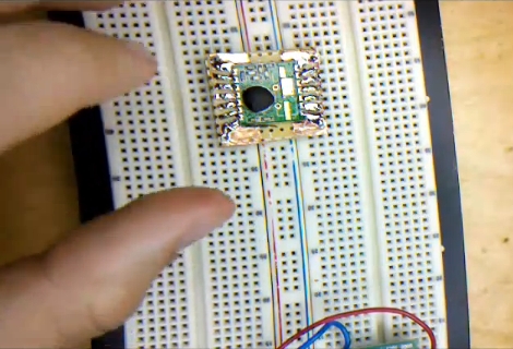
[Caleb] needed to use some surface mount components when prototyping. Instead of buy a breakout board he made one himself without doing any etching. The process he shows off in the video after the break uses copper tape to layout the traces for the board. It’s quite an interesting method which requires a sharp knife and a steady hand.
He used regular protoboard as a substrate and applied a layer of copper tape on the side without copper pads. From there he poked holes for the DIP pin headers. Now it’s time to do some cutting. [Caleb] removed the band of copper that would fall in between the pins of the surface mount device. He then tacked it in place with one dot of solder and drew the traces from the part to the pin headers. After removing the part he cut out the waste in between each line he drew with marker. What he’s left with is a set of thin traces that connect each pin of the surface mount component to the corresponding through-hole pin header.
This is very time-consuming, but then again so is soldering jumper wires to small-pitch components.


