The Flexible Permanence Of Copper Tape Circuits

Somewhere between shoving components into a breadboard temporarily and committing them to a piece of protoboard or a PCB lies the copper tape method. This flexible Manhattan-style method of circuitry formed the basis for [Bunnie Huang]’s Chibitronics startup, and has since inspired many to stop etching boards and start fetching hoards of copper tape.

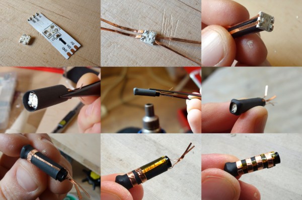
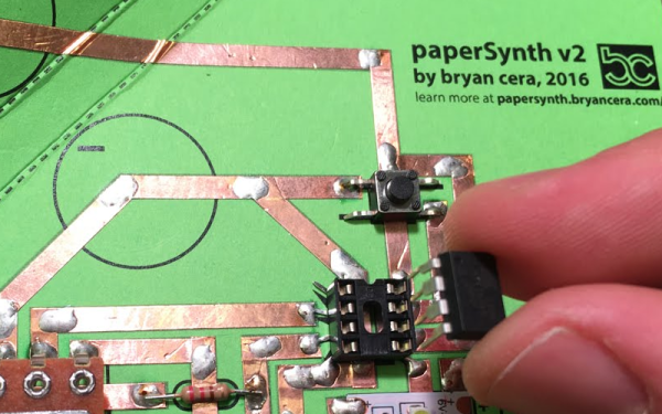
[Hales] hit the ground running when he learned about this method, and has made many a copper tape circuit in the last year or so. He offers several nice tips on his site that speak from experience with this method, and he’ll even show you how to easily work an SMD breakout board into the mix.

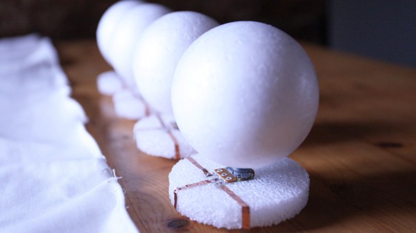
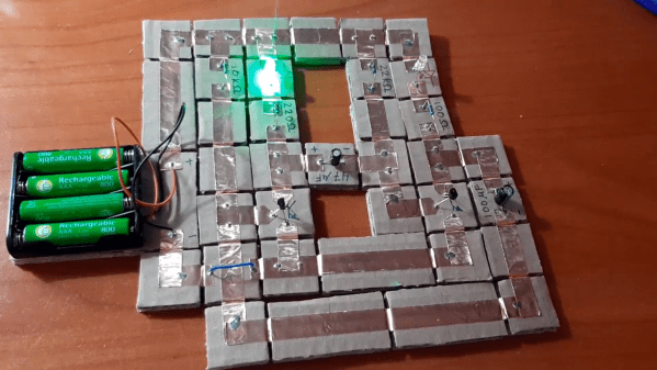
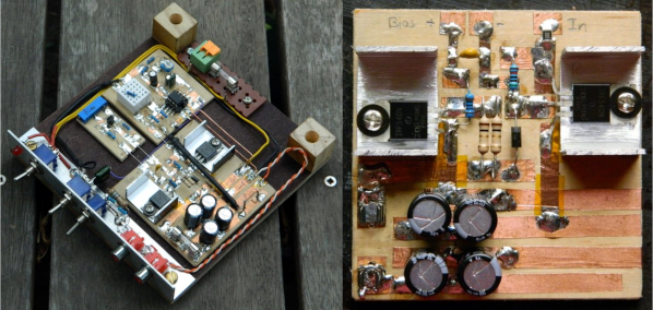
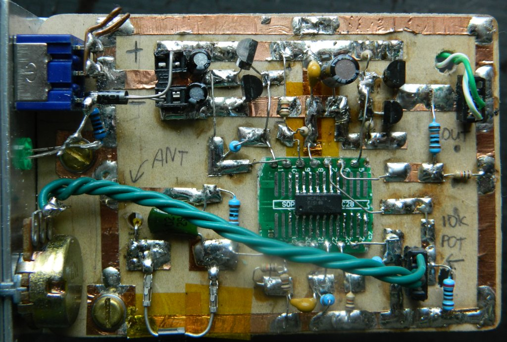
Generally speaking, [Hales] prefers plywood as the substrate to paper or cardboard for durability. He starts by drawing out the circuit and planning where all the tape traces will go and how wide they need to be. Then he lays out copper traces and pads, rubs the tape against the substrate to make it adhere strongly, and reinforces joints and laps with solder before adding the components. As you can see, copper tape circuits can get pretty complicated if you use Kapton tape as insulation between stacked layers of traces.

Copper and Kapton (polyimide) tape are just two of the many useful tapes you may not be aware of. Stick with us a moment and check out [Nava Whiteford]’s exploration of various adhesive marvels.

Fabric(ated) Drum Machine

Some folks bring out an heirloom table runner when they have company, but what if you sewed your own and made it musical? We’d never put it away! [kAi CHENG] has an Instructable about how to recreate his melodic material, and there is a link to his website, which describes his design process, not just the finished product. We have a video below showing a jam session where he exercises a basic function set.

GarageBand is his DAW of choice, which receives translated MIDI from a Lilypad. If you don’t have a Lilypad, any Arduino based on the ATmega328P chip should work seamlessly. Testing shows that conductive threads in the soft circuit results in an occasional short circuit, but copper tape makes a good conductor  at the intersections. Wide metallic strips make for tolerant landing pads beneath modular potentiometers fitted with inviting foam knobs. Each twist controls a loop in GarageBand, and there is a pressure-sensitive pad to change the soundset. Of course, since this is all over MIDI, you can customize to your heart’s content.

MIDI drums come in all shapes and sizes, from a familiar game controller to hand rakes.

Continue reading “Fabric(ated) Drum Machine”

Magnetic Circuits Are More Attractive Than Breadboarding

Let’s face it, breadboarding can be frustrating, even for advanced electronics wizards. If you have an older board, you could be dealing with loose tie points left from large component legs, and power rails of questionable continuity. Conversely, it can be hard to jam just-made jumper wires into new boards without crumpling the copper. And no matter what the condition of the board is, once you’ve plugged in more than a few components, the circuit becomes hard to follow, much less troubleshoot when things go pear-shaped.

In the last twenty years or so, we’ve seen systems like Snap Circuits and Little Bits emerge that simplify the circuit building process by making the connections more intuitive and LEGO-like than even those 160-in-1 kits where you shove component legs between the coils of tight little springs. You will pay handsomely for this connective convenience. But why should you? Just make your own circuit blocks with cardboard, magnets, and copper tape. It should only cost about 10¢ each, as long as you source your magnets cheaply.

[rgco] gives the lowdown on building a minimal set of 23 component and connector blocks using 100 magnets. He’s got 11 example circuits to get you started, and some example videos of more advanced circuits that got tacked up after the break.

This method of making the circuit look more like the schematic may be the best way for the visually-inclined to learn electronics. But the best way to learn electronics depends on where you’re coming from.

Continue reading “Magnetic Circuits Are More Attractive Than Breadboarding”

Three-Conductor Pivot For E-Textiles Is Better Than Wires

Pivots for e-textiles can seem like a trivial problem. After all, wires and fabrics bend and flex just fine. However, things that are worn on a body can have trickier needs. Snap connectors are the usual way to get both an electrical connection and a pivot point, but they provide only a single conductor. When [KOBAKANT] had a need for a pivoting connection with three electrical conductors, they came up with a design that did exactly that by using a flexible circuit board integrated to a single button snap.

This interesting design is part of a solution to a specific requirement, which is to accurately measure hand movements. The photo shows two strips connected together, which pivot as one. The metal disk near the center is a magnet, and underneath it is a Hall effect sensor. When the wrist bends, the magnet is moved nearer or further from the sensor and the unit flexes and pivots smoothly in response. The brief videos embedded below make it clear how the whole thing works.

Continue reading “Three-Conductor Pivot For E-Textiles Is Better Than Wires”

Bumblebee Breakout, A DIY Wearable Connector

The practice of developing wearable electronics offers a lot of opportunity for new connector designs and techniques for embedding electronics. Questions like these will eventually come up: How will this PCB attach to that conductive fabric circuit reliably? What’s the best way to transition from wire to this woven conductive trim? What’s the best way to integrate this light element into this garment while still maintaining flexibility?

Mika Satomi and Hannah-Perner Wilson of Kobakant are innovators in this arena and inspire many with their prolific documentation while they ask themselves questions similar to these. Their work is always geared towards accessibility and the ability to recreate what they have designed. Their most recent documented connector is one they call the Bumblebee Breakout. It connects an SMD addressable RGB LED, such as Adafruit’s Neopixel, to a piece of side glow fiber optic 1.5mm in diameter. On a short piece of tubing, the four pads of the SMD LED are broken out into four copper rings giving it the look of a striped bumblebee. To keep from shorts occurring while wrapping the copper tape contacts around the tube, they use Kapton tape to isolate each layer as they go.

This connector was originally created to be used in a commission they did out of Koba, their e-textile tailor shop located in Berlin. Fiber optics were applied to jackets for a performance called “All Your Base Are Belong To Us” produced by the Puppetry Department of the Hochschule für Schauspielkunst Ernst Busch.

Peruse more e-textiles techniques and learn how to build a connector transitioning from an embroidered thread bus to a wire and how to knit solderable circuit boards. And make sure to click around Kobakant’s website, it’s full of e-textile DIY tutorials! 

Edgytokei

Edgytokei’s Incredible Mechanism Shows Time Without A Face

Taking inspiration from Japanese nunchucks, [ekaggrat singh kalsi] came up with a brilliant clock that tells time using only hour and minute hands, and of course a base for them to sit on. The hands at certain parts of the hour seem to float in the air, or as he puts it, to sit on their edges, hence the name, the Edgytokei, translating as “edge clock”.

The time is a little difficult to read at first unless you’ve drawn in a clock face with numbers as we’ve done here. 9:02 and 9:54 are simple enough, but 9:20 and 9:33 can be difficult to translate into a time at first glance. Since both hands have to be the same length for the mechanism to work, how do you tell the two hands apart? [ekaggrat] included a ring of LEDs in the hub at the base and another at the end of one of the hands. Whichever ring of LEDs is turned on, indicates the tip of the minute hand. But the best way to get an idea of how it works is to watch it action in the video below.

We have to admire the simplicity and cleanliness of his implementation. The elbow and the hub at the base each hide a stepper motor with attached gear. Gear tracks lining the interior of the hands’ interact with the motor gears to move the hands. And to keep things clean, power is transferred using copper tape lining the exteriors.

On the Hackaday.io page [ekaggrat] talks about how difficult it was to come up with the algorithms and especially the code for homing the hands to the 12:00 position, given that homing can be initiated while the hands can be in any orientation. The hand positions are encoded in G-code, and a borrowed G-code parser running on an Arduino Nano in the base controls it all.

Continue reading “Edgytokei’s Incredible Mechanism Shows Time Without A Face”

Copper Foil Makes Music–With A Little Help

Craft stores are often the source of odd inspiration. In the stained glass section, we’ve seen the copper foil, and even used it to prototype some RF circuits on the tops of shoeboxes. However, we could never get a good method for connecting ICs to the relatively thick foil. [Bryan Cera] did it though. His paperSynth uses some paper and cardboard for a substrate, copper foil, and an ATtiny CPU to make music. You can see the device in operation in the video, below.

The copper foil is sticky and it isn’t conductive on the back, so anywhere the foil is supposed to touch, you need a blob of solder. We wouldn’t trust the insulation by itself to cross wires, but with a bit of insulating material between–a piece of paper or electrical tape, for example–you could probably cross with impunity. For an RF circuit, you might even make low-value capacitors like that.

Continue reading “Copper Foil Makes Music–With A Little Help”