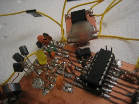
Radio communications depend on stable oscillator frequencies and with that in mind, [Scott Harden] built a module to regulate temperature of a crystal oscillator. The process is outlined in the video after the break but it goes something like this: A small square of double-sided copper-clad board is used as a base. The body of the crystal oscillator is mounted on one side of this base. On the other side there is a mosfet and a thermister. The resistance of the thermister turns the mosfet on and off in an attempt to maintain a steady temperature.
This is the first iteration of [Scott’s] crystal oven. It’s being designed for use outdoors, as his indoor setup uses a styrofoam box to insulate the oscillator from ambient temperatures. He’s already working on a second version, and mentioned the incorporation of a Wheatstone bridge but we’ll have to wait to get more details.


