Fixing A Malfunctioning Keithley Model 179 Digital Multimeter

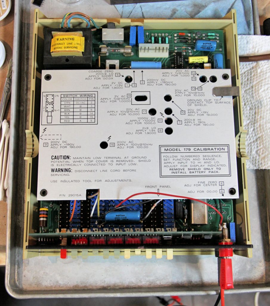
Inspired by electronics repair videos on YouTube, [Steven Leibson] recently found himself hunting down something to fix on eBay. This ‘something’ ended up being a  certified classic: a Keithley Model 179 digital multimeter from 1978. Listed as non-functional, the unit arrived at his door for less than $50. There weren’t any exciting pops or smoke when he powered it on, but the display seemed to be showing nothing but random nonsense.

The Keithley Model 179 multimeter has a convenient calibration sequence printed on its electrostatic shield cover and a deadly exposed ac line fuse in the upper left part of the photo. (Image credit: Steven Leibson)
The meter has a convenient calibration sequence printed on its electrostatic shield cover and a deadly exposed AC line fuse in the upper left part of the photo.

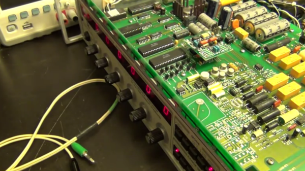
Ultimately reviving this little piece of history was quite simple, with the main issue turning out to be a dodgy inter-board connector between the main and display boards. After admiring an old repair attempt made on the component, he removed both the male and female connectors, replacing them with new ones.

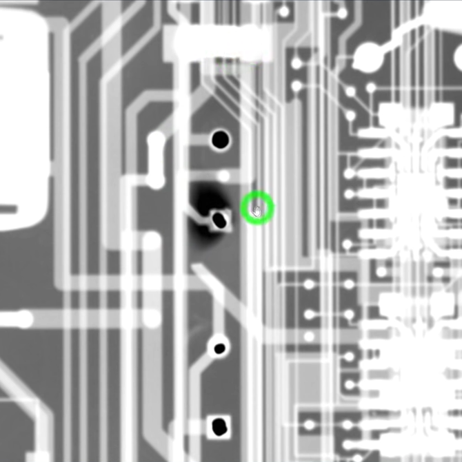
This uncovered issues with the PCB, as the FR4 material and the traces on it had begun to delaminate, probably due to the old adhesive giving up due to age. With pretty low trace density this wasn’t anything that a bit of care couldn’t work around, fortunately.

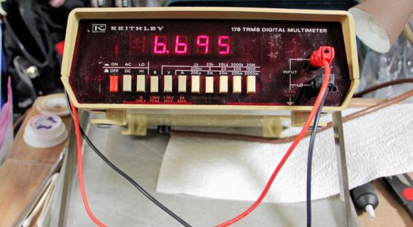
Before finding this dodgy connector, [Steven] first tried to clean the front mechanical connectors, which took multiple sessions. This was followed up by oiling the mechanism. With the connector fixed and some cleaning, the meter’s display now read correctly. It still has some issues with starting up though, which [Steven] reckons are due to the old capacitors in the device.

Presumably some recapping will round off this fun device revival experience, but for the time being a Keithley Model 179 has been saved from e-waste, to inspire generations to come.

Vintage Meter Repair? It’s Easier With X-Rays

Here’s an interesting and detailed teardown and repair of a Keithley 2001 7.5 Digit multimeter that is positively dripping with detail. It’s also not every day that we get to see someone using x-ray imaging to evaluate the extent of PCB damage caused by failed electrolytic capacitors.

Dark area is evidence of damage in the multi-layer PCB.

Sadly, this particular model is especially subject to that exact vintage electronics issue: electrolytic capacitor failure and leakage. These failures can lead to destroyed traces, and this particular unit had a number of them (in addition to a few destroyed diodes, just for good measure.) That’s where the x-ray machine comes in handy, because some of the damage is hidden inside the multi-layer PCBs.

[Shahriar], perhaps best known as [The Signal Path], narrates the entire process of fixing up the high-quality benchtop multimeter in a video, embedded below (or you can skip directly to the x-ray machine being broken out.) [Shahriar] was able to repair the device, thanks in part to it being in relatively good shape, and having the right tools available. Older electronics are not always so cooperative; the older a device is, the more likely one is to run into physical and logical standards that no longer exist.

Continue reading “Vintage Meter Repair? It’s Easier With X-Rays”

Repair And Calibration Of Valhalla Programmable Precision Standard

Precision standards are the pinnacle of test and measuring instrumentation. Well engineered, sure, but also beautifully built and a feast to look at, no matter how old they are. [Shahriar] at “The Signal Path” often gives us the skinny on such equipment. In the latest episode, we get a look inside a Valhalla 2701C Programmable Precision DC Voltage Standard.

Even by 1990 standards, it is a fairly basic instrument, capable of producing just DC Voltages from 100nV up to 1200V. But it is a reference standard, so the output is highly stable, accurate and precise.  He snagged it from eBay on the cheap but transport seemed to have caused some damage. It would switch on and relays would click when he pressed buttons, but the 7-segment LED display was blank. Luckily, opening the top cover fixes that problem – just a loose connection between the front display and the main board. Examination also shows that adding a 120mA DC current range would require adding additional components on the main board so his hope of doing a quick firmware upgrade is short lived.

[Shahriar] takes the opportunity to walk us through the various sections of the well built unit. It’s apparently seen some repairs during it’s life. A few capacitors look changed, and a relay housing has seen damage from a soldering iron. The digital section is mainly the 6800 micro controller, an EPROM and a NVRAM, and it generates the PWM signals needed for producing the output voltages. A highly precise reference signal is essential for such equipment, and this one uses the LM299 with a “custom” suffix meaning it was specially screened and binned. He does a quick calibration run, but it’s obviously rushed and doesn’t produce stable results. But that could also be due to the low quality cables he used, or a number of other factors. Calibrating such equipment is a job demanding both time and patience.

While this may not knock your socks off. For that, check out this post where [Shahriar] does a tear down of the one million dollar Labmaster 10-100zi Oscilloscope, or this other one where he plays around with a half a million dollar oscilloscope you’ll probably never use, much less own.

Continue reading “Repair And Calibration Of Valhalla Programmable Precision Standard”