
Today we’ll take a journey into less noisy noise, and leave behind the comfortable digital world that we’ve been living in. The payoff? Smoother sounds, because today we start our trip into analog.
If you remember back to our first session when I was explaining how the basic oscillator loads and unloads a capacitor, triggering the output high or low when it crosses two different thresholds. At the time, we pointed out that there was a triangle waveform being generated, but that you’d have a hard time amplifying it without buffering. Today we buffer, and get that triangle wave out to our amplifiers.
But as long as we’re amplifying, we might as well overdrive the amps and head off to the land of distortion. We’ll do just that and build up a triangle-wave oscillator that can morph into a square wave, passing through a rounded-over kinda square wave along the way. The triangle sounds nice and mellow, and the square wave sounds bright and noisy. (You should be used to them by now…) And we get everything in between.
And while we’re at it, we might as well turn the triangle wave into a sawtooth for that nice buzzy-bass sound. Then we can turn the fat sawtooth into a much brighter sounding pulse wave, a near cousin of the square wave above.
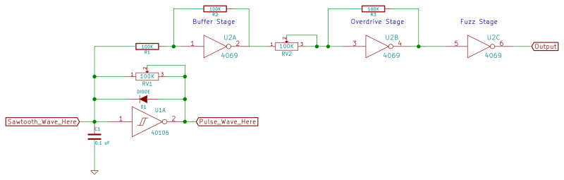
What’s making all this work for us? Some dead-boring amplification with negative feedback, and the (mis-)use of a logic chip to get it. After the break I’ll introduce our Chip of the Day: the 4069UB.
If you somehow missed them, here are the first three installments of Logic Noise:
The 4069UB
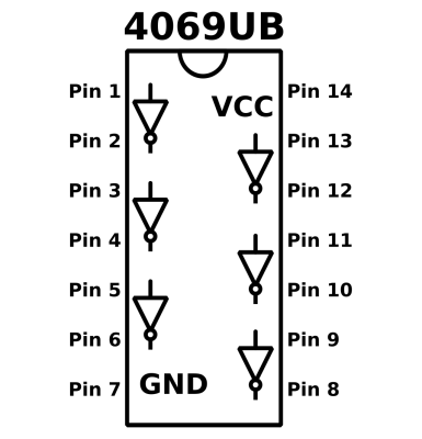 The 4069UB is a hex (unbuffered) inverter. In fact, if you can remember the pinout of the 40106, this should look very familiar to you. The only difference is the lack of hysteresis (and the little squiggly symbols) in the inverters. But what a difference that makes! The lack of buffering and hysteresis in the inverter lets us use the individual amplifiers for analog purposes rather than digital / logic.
Remember that the “UB” part is mandatory for all of this to work. It stands for unbuffered, and that essentially means that there’s no special attempt made to convert the output into something digital inside the chip. (Some end in “UBE” or “UBF” or whatever. As long as there’s a “UB” somewhere, you’re set.) And it turns out that an unbuffered inverter is nothing more than a push-pull CMOS amplifier pair. Each “inverter” cell looks like this:
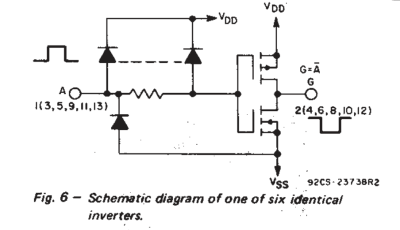
Ignoring the input-protection diodes, you can see that it’s basically just two transistors: an N-channel FET connected between output and ground and a P-channel FET connected between output and the power rail. (That’s the Complementary MOS pair that gives CMOS chips their name.)
If you’re not brushed up on your MOSFETs, the N-channel conducts when the input gate is pulled to a high voltage, and the P-channel conducts when the input gate is pulled low. This means that when the input voltage is low, the bottom FET doesn’t conduct and the top FET does, pulling the output voltage high. And vice-versa for a high input voltage. This makes a rudimentary logic inverter. Hooray!
But what happens in-between? At mid-supply voltages, both of the transistors will be turned on to varying degrees. This makes an output voltage that’s continuous, analog, and the “opposite” of the input. In order to give the chip a decent logic output, it needs to have a high gain through this middle zone so that voltages that are just a bit higher than the midpoint result in outputs that are clearly a logic zero.
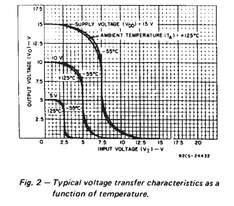
The beauty of this chip for our purposes is the soft clipping effect that you get from the S-shaped gain curve above. That is, the gain rolls off (the line is less steep) near VCC and GND. This makes for a pleasing overdrive sound as we crank the amplifier up, and lets us control the amount of fuzz on the output by controlling the input volume and gain.
Buffers and Feedback
As we said above, the naked 4096UB chip has a very high gain right around the midpoint voltage, which is what makes it useful as a logic chip. To make it useful for amplifiying analog audio, we’ll use (negative) feedback to calm this gain down a little bit. By controlling the ratio of input signal to feedback, we can vary the output from nearly completely silent to distorted out to the limits of the voltage supply.
For starters, let’s aim to get a voltage gain of -1. That is, the output signal is just as big as the input signal but opposite in sign around the mid-point. This is an “inverting unity gain buffer” if you’re an electrical engineer. And buffers will allow us to listen in to signals that our amplifier’s input circuitry would otherwise swamp out.
Remember when we said that there was a triangle wave on the input terminals of the 40106 inverter? Did you try to plug them up to your amplifier? If so, it probably didn’t work although you can see it clear as day on the oscilloscope. Even when I can get it to work, there’s still a pitch shift that depends on the volume knob settings on my amplifier. Strange stuff! Clearly, the amplifier’s input circuitry is coupling with the oscillator. Putting a buffer circuit in-between will let the oscillator oscillate and the amplifier amplify without interacting with each other. That’s what buffers do. Let’s build.
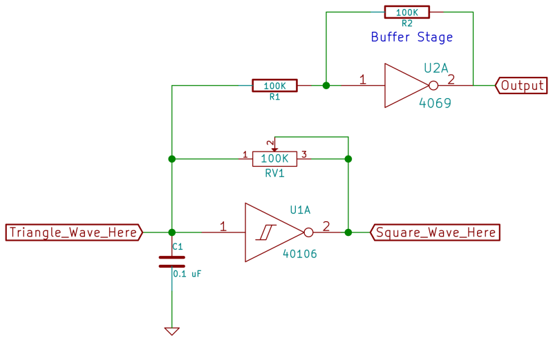
The unity-gain buffer circuit is as simple as connecting the input through a resistor and then connecting another resistor with that same value in feedback between the output and the input. For intuition on how this works, let’s dig briefly into negative feedback amplifiers.
The intuition for this circuit (and all negative feedback topologies) involves first realizing that where the input signal and negative feedback meet, there can’t be any net signal voltage above or below the chip’s neutral voltage. If there were positive net signal, the inverter output would go negative until the feedback brought the junction of the two back down to neutral. If the input is negative with respect to neutral, the output will go positive and pull it back up. When the feedback path is working as intended, it’ll hold the input at the neutral voltage level.
A quick word about this neutral voltage. If you’re familiar with op amps, the neutral voltage is whatever’s present on the positive terminal. In our case, the chip switches from high to low around the mid-rail voltage, half of VCC, so that’s our neutral point. You can demonstrate this by unplugging the input and measuring what voltage level the output (and input) settle at with no signal present. It’ll be around VCC/2.
 So the first basic premise is that the feedback exactly cancels out the net signal where they meet up at the input of the inverter. This cancellation means that whatever signal current comes in through the input resistor has to get pulled on out through the feedback resistor. If you think of voltage as the force required to push a given current through a resistor, the output only has to work as hard as the input when the two resistors are equal. That is, when the input voltage is 0.1 volts above neutral, the output will be 0.1 volts below neutral because both are “fighting” the same resistance.
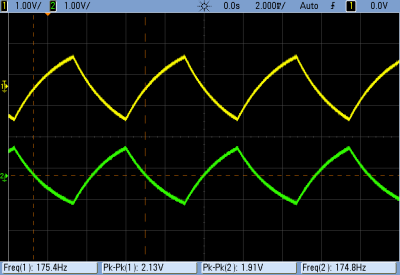
And there you have it: an “amplifier” with a gain of negative one. It doesn’t make the signal louder, but now you can plug the output of the buffer stage directly into your audio output and give it a listen without interference. And just for fun, this picture shows the input and output on the scope. Working as intended.
Amplifiers and Overdrive
Great. Now we’ve got a nice clean triangle wave oscillator. You’d think we were done here, but we still have five inverter gates sitting unused on the 4069UB. What could we do with five more amplifiers? Five more amplifiers that have a nice smooth rolloff much like old-school tube preamps do? Crank it up to 11 and see how it sounds!
To go from buffer circuit to amplifier circuit, we can either let the input signal flow in more easily (reduce the input resistance) or force the output to work harder (increase the feedback resistance). Either way, the goal is to increase the ratio of feedback resistor to input resistor, and thus the voltage gain.
So let’s build up another buffer circuit, but instead of a 100k Ohm resistor on the input, let’s use a 100k potentiometer so that we can let more signal in. Now it’s an amplifier, with the gain controlled by the ratio of the feedback resistor (at 100k Ohms) divided by whatever resistance we dial in on the input potentiometer. (You could use a larger pot than feedback resistor, and you’d be able to make the circuit quieter as well. But that’s boring.)
As you drop the input resistance down to zero, you’d naively expect the amplification gain to head off to infinity. Instead, we see that the gain reduces gradually as the output voltage approaches the GND or VCC power rails. What happens is that real-world effects like the chip’s amplification rolloff take over. Is this a bad thing? Not if you want a nice soft-clipping amplifier overdrive sound added to our triangle wave. Woot.
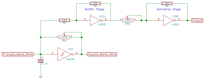
Now as long as we have a bunch of free inverters sitting around, let’s take the output from the overdrive sound and re-amplify it again. The IC’s built-in soft clipping will limit the volume gain, but we’ll get something that’s ever more like a square wave as we keep passing the signal through further amplification stages. Note that the fuzz stage runs at full gain — without negative feedback. We’re going for fuzz distortion here. For my liking, a single extra amp stage suffices to get a nice fuzz tone, but you could chain up as many stages with and without feedback as you want. Heck, half of the chip is still sitting there unused, go nuts.
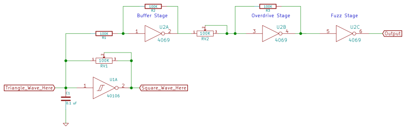
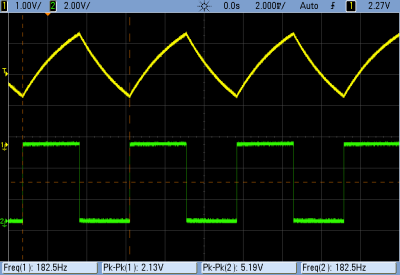
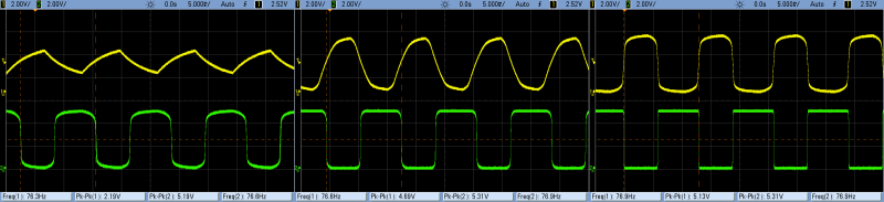
Here are some example waveforms from the first-stage amplifier and the second. At the low-gain end of things, you can see that the first-stage triangle wave, in yellow, is not very distorted yet. But as we turn up the gain, the points get rounded over on top and it approaches a round square wave. (“Round square”?) The second-stage output, in green, starts off pretty much squared-out and gets more so. Between the two outputs, you have mild overdrive and full fuzz. Can’t complain about that.
The scope traces below show the overdrive output in yellow and the fuzz output in green with the volume knob turned increasingly up. You can see that the as you increase the gain, the fuzz channel takes off essentially where the overdrive channel leaves off.
And don’t hesitate to feed other audio sources into this chip. A version of this circuit dates back to the late 1970’s, known as [Craig Anderton’s] “Tube Sound Fuzz” from his book Electronic Projects for Musicians. My wasted youth doesn’t look so wasted anymore, huh?
Sawtooth Waves
OK, so we’ve got a nice variable overdrive version of the triangle wave oscillator. What else can we do with our newfound analog powers? Here, the most bang for our breadboard buck is to add a diode into the feedback path of the oscillator, turning the triangle wave into a sawtooth.
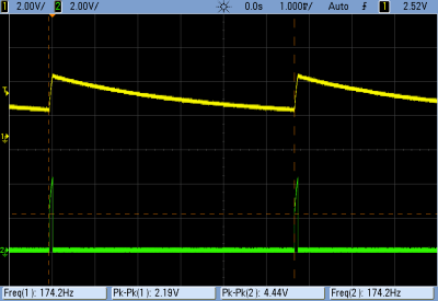
How does that work? Well, instead of charging and discharging the timing capacitor through the feedback resistor as we’ve been doing, we charge it much faster through the diode. This makes the input voltage jump up, setting the output low almost instantly. The diode only conducts in the charging direction, so the capacitor has to discharge slowly through the feedback resistor. This goes on until it hits the threshold value where the output goes high again and charges up the capacitor very quickly through the diode again. In short, we’ll end up with a voltage waveform on the input here in yellow, and on the output here in green:
Now all that’s left to do is pass this sawtooth through the buffer amplifier above. That’s that raspy, bowed-string sound that a sawtooth wave makes. Played down low, you get the classic acid-house bassline. Go nuts. But wait, there’s more. We have a sawtooth plus overdrive, plus full-on fuzz.
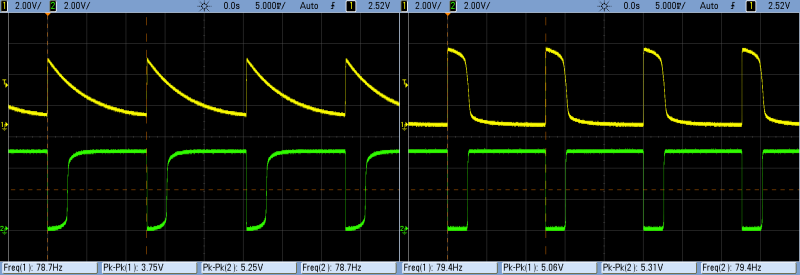
Below is the scope trace from medium and full gain for the overdrive output in yellow and the fuzz output in green. With the sawtooth wave, the fuzz ends up converting the sawtooth into a kind of pulse wave. It’s not symmetrically square both because our sawtooth isn’t perfectly straight and because there’s some DC offset voltage propagating through the three stages that we haven’t been careful with. If you want to remove that, you can insert something like 0.1uF blocking capacitors between the stages, but I feel you lose some of the gritty character of this thing by doing so.
Next Installment: Filters and Drums
Now that we have some classic analog synth waveforms under our belts, it’s time to add some filter effects and drums. To do so, we’ll continue down the analog path that we started this time, so if you don’t already have a couple of 4069UBs at hand, you have another week to scrounge some up.


its more powerfull 4049
It would be nice to have some kind of sound reference at the beginning of the video.
I hit the play button on the video, saw subtitles and expected spoken word as well, but I couldn’t hear anything, so I cranked up the volume on amplifier. Then, when you connected oscillator, it made beep so loud I almost pissed my pants.
Anyway, I love this original HaD content.
That’s a great idea, especially for the intro videos. Will do that for next installment! Thanks.
And the reason that they’re totally quiet to start, and the reason that I’m using subtitles, is that the audio you hear is a direct feed into my laptop’s line in. So there’s no background noise at all, and it sounds great on good headphones.
About 1 minute into the sawtooth video it sounds like an .049 airplane engine.
i was just thinking today about putting the square wave into an integrating op amp to make a saw wave. And maybe if you offset the square wave down it could be a triangle wave, i’m not really sure if that’s how the integrating op amps work. Then i see this! I am really loving this series.
Yeah. That’s essentially the classic sawtooth oscillator: constant current source into an integrator, and clear the cap when the voltage hits some threshold.
When you’re trying to get precise pitches, the time it takes to reset the cap is important (you want it nearly instantaneous) and getting good voltage-control over the input current is key. The third image down here (http://www.analogcreations.com/vco.html) is the classic sawtooth core. It uses a JFET instead of the diode to do the resetting, and the circuit is designed around +/- voltage supply, but it’s basically the same idea.
But for quick-and-dirty? I’m saying this is about the best bang-for-buck around. Maybe you could gang up several oscillators together on the 40106 to push more current through the diode or use a schottky diode to speed up the fall time. But meh. Good enough!
Ah thanks for the link i will hopefully be able to understand these circuits sometime soon. If i put a square wave into two integrators i guess i would get a sine wave too. Also i will be trying your way too, this is the first of your chips not available at my local jaycar (sydney Aus) but they do seem to have a few UB inverters so i’m going to have a look at them all and try one. Or i could order it online…
ah yes that website has triangle – sine at the bottom.
Correction jay car do have it just no UB in the part number
Our laboratory has taken and imported it.
This procedure involves the burning of the top layer of skin to promote new collagen production. A good majority move down from the cold up north to our beautiful, white sandy beaches. Of course, the traditional winter recipes work well too and the advantage for me of having a large slow cooker for our small family is that I can double the quantities and make two meals, one of which I can freeze for another day.
Can you explain how to connect a CV in to the circuit?
Three years too late! (I’m going back through the series now for a talk.)
To control the pitch, you want to slow down the capacitor charging/discharging. This is actually very easy with the sawtooth circuit: adding in more charging current, say through a resistor, will increase the pitch. Routing this extra current through a transistor can give you voltage control.
Like so: http://electro-music.com/forum/topic-28799.html
Why inverter amplifies only triangle wave output of pin 1 with capacitor. If you try to amplifiy square wave coming from pin 2 (output of oscillator), the voltage level of square wave signal is at best 100% equal. (checked with oscilloscope). Thanks in advance.