Tilt Compensation When Reading A Digital Compass

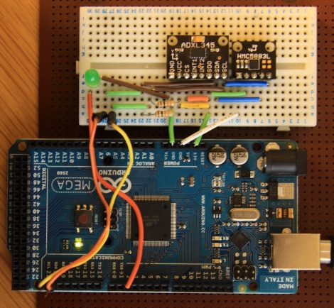
If you’re familiar with using a compass (the tool that points to magnetic north, not the one that makes circles) the concept of holding the device level makes sense. It must be level for the needle to balance and rotate freely. You just use your eyes to make sure you’re holding the thing right. Now think of a digital compass. They work by measuring the pull of a magnetic field, and have no visual method of showing whether they’re level or not. To ensure accurate readings you might use an accelerometer to compensate for a tilted magnetometer.

The process involves taking measurements from both an accelerometer and a magnetometer, then performing calculations with that data to get a true reading. Luckily the equations have been figured out for us and we don’t need to get too deep into trigonometry. You will, however, need to use sine, cosine, and arctangent in your calculations. These should be available in your programming language of choice. Arduino (used here) makes use of the avr-libc math library to perform the calculations.

A Beginner’s Guide To Magnetometers

magnetometers_for_beginners

The folks over at LoveElectronics recently published an article that explains some of the ins and outs of magnetometers for those who are interested in trying one out, but might not understand how to use them.

A good part of the article focuses specifically on how to manipulate the HMC5883L magnetometer from Honeywell, but a lot of the information can be applied to other makes/brands of compass sensors. They start out discussing in very basic terms how the compass works, then delve into some specifics on how to interface the chip with an Arduino, courtesy of a breakout board that they sell. The breakout board is actually quite simple, so any number of custom iterations could be built for your own testing purposes.

They walk through the use of an HMC5883L-specific Arduino sketch they produced, making it easy for beginners to start getting useful data from the compass units. While a pre-made sketch might seem like a bit of a cop out, it at least gives the curious/motivated beginner a chance to look at some completed code in order to see how things work.

If you are interested in cutting your teeth on some additional beginner concepts, check out these other how-to articles and tutorials.

3D Magnetometer Mouse In Processing

FFB4SV5G0SD7J7G_MEDIUM

[etgalim] works in Solidworks extensively and wanted a more intuitive way of rotating objects onscreen. To do this, he created a mouse that responds to rotation. He put a 3D compass module inside an old mouse and wired it up to an Arduino. The Arduino then relays the I2C sensor data to the computer. So far, he has a Processing script that uses the mouse to rotate a cube, but eventually he wants to write a Solidworks plugin. It’s a bit shaky, and we think it would be a bit smoother (and cheaper) if he used gyros like the jedipad. Video after the jump.

Continue reading “3D Magnetometer Mouse In Processing”