[John] is working on his PhD in experimental earthquake physics, and with that comes all the trials of becoming a PhD; tuning students into the cool stuff in the field, and demonstrating tech created after 1970 to his advisers. One of the biggest advancements in his line of work in the last 30 or 40 years is all those sensors you can find in your cell phone. The three-axis magnetometer in your phone is easily capable of measuring the Earth’s magnetic field, and this chip only costs a few dollars. To demonstrate this, [John] built a 3D compass to show off the capability of these sensors, and have a pretty light show for the undergrads.
The magnetometer [John] is using is just a simple I2C magnetometer that can be found on Adafruit or Sparkfun. It’s not really anything special, but with a little bit of code, [John] can read the magnetic field strength in the x, y, and z axes.
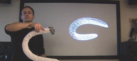
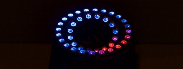
Having a microcontroller spit out a bunch of numbers related to the local magnetic field just doesn’t seem fun, so [John] picked up two neopixel rings – one inside the other, and set 90 degrees out of plane with each other. This turns his magnetometer and Arduino setup into a real 3D compass. With this device, the local magnetic field can be visualized in the x, y, and z axes. It looks cool, which is great for undergrads, and it’s a great demonstration of what you can do with small, cheap electronic sensors.
[John] put up a screencast of a talk he gave at the American Geophysical Union meeting last year. You can check that out below.