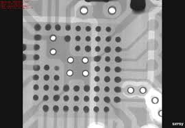
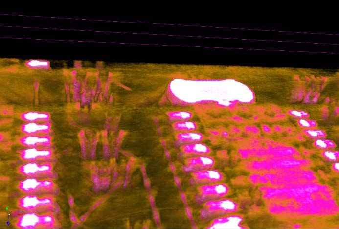
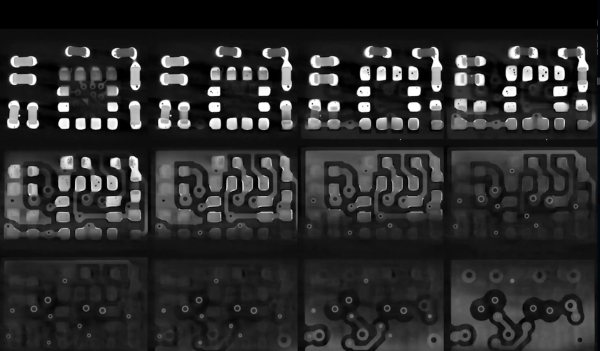
At risk of getting any ASMR buffs who might be reading cranky because there’s no audio, [Chris], or [@no1089] on Twitter, has gifted us with this visually stunning scan of his Maxim MAX86160 in-ear heart monitor mounted on a rigidflex PCB. You can take a look, in the video below the break.
If you’re wondering why anyone would scan a board, other than boredom, know that it’s actually quite common. X-Ray machines are commonly used as a quick, passive way to check a board that’s fresh off the production line. These aren’t the X-Rays like those of broken bones you’re (hopefully not too) used to seeing though, they’re Computed Tomography scans (CT scans, CAT scans), in effect just 3D X-Rays.

For electronics manufacturers and assemblers, CT scans are incredibly useful because they provide a non-destructive way to check for errors. For example, how do you know if that middle BGA pin is actually soldered correctly? You could run a functional test and make sure everything is working (at least, everything you check), but that takes time. The longer it takes to validate, the higher the manufacturing cost. In manager speak: “cost bad. Fast good.”
It’s also common to use a CT scan to create a full 3D model of a board. This makes it easy to check every little detail, especially the ones that are visually obscured by surface mount devices or critical signal paths that are buried under board layers.

If you want to geek out on CT scans, you can learn more about the lab that did this scan or by wading into this unclassified research paper from Australia’s Cyber and Electronic Warfare Division.
But we know you really want more of this video, but better. And we’ve got the goods. For the chill folk among you, here’s a 55-minute version without all the CT scan info cluttering the screen. For those of you currently blasting eDM in your headphones, here’s a 30 second clip of it looping at ~5x speed. Eat your heart out:
Continue reading “This CT Scan Of A PCB Is The Accidental ASMR We Didn’t Know We Needed”


