Well, we have to admit, we never saw this coming… A 3D printed lawn mower? What? Why? Huh? How? Those were at least a few of the thoughts running through our head when we saw this come in on the tips line.
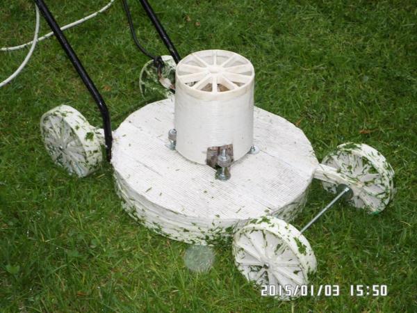
[Hans Fouche] has a giant 3D printer that takes up most of the space in his garage, and after printing several large vases, a briefcase, bowls, and even a wind turbine blade — he decided to try printing a lawnmower. A freaking lawnmower.
To do so, he reverse engineered his old rusty lawn mower, and redesigned it to be printable. Apart from the steel axles, some fastening hardware, and of course the motor and blade, the entire thing is 3D printed. And it looks like it works pretty good too.
[Stephen] used a solid state relay he found on eBay to drive some Christmas lights. The SSR failed. That meant it was time to see inside of this relay looked like. The short answer is, ‘a lot of goop and epoxy’, but the traces look big enough to support the current it’s rated for.
The Electronica MK-54 and MK-61 (actually the Электроника МК-54) were incredibly popular Soviet programmable calculators. Now there’s an emulator for them.
[Rue Mohr] found a very cheap TFT display on an Arduino shield. The chip for the display was an SPF5408, a chip that isn’t supported by the most common libraries. He eventually got it to work after emailing the seller, getting some libraries, and renaming and moving a bunch of stuff. If you have one of these displays, [Rue] just saved you a bunch of time.
The Hackaday European tour continues, this time in Prague with Josef Průša (Google translate), core developer in the RepRap project, feature at all the Maker Faires and cons, and creator of his namesake, the Prusa Mendel and i3 printers.
[Prusa]’s involvement with the RepRap project started with a RepRap Mendel, the second iteration of RepRap hardware, but the first popular and easy to build version. [Jo] found the Mendel rather difficult to build, so he loaded OpenSCAD and started to design his own version of the hardware. This version became the de facto standard RepRap for a few years, with many inspired by and derivative printers making their way to hackerspaces and workshops around the world.
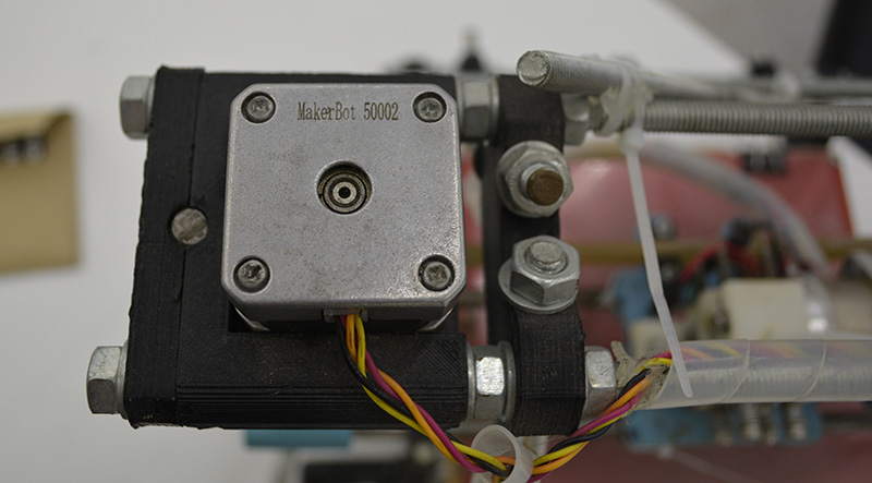
The first Prusa printer, derived from the RepRap Mendel.
A few years ago, [Prusa] was one of the first to make a complete break with the traditional ‘threaded rod and nut’ construction of RepRaps with the introduction of the Prusa i3. This was the first model that had a metal plate as the frame, another feature that would be seen in dozens of other models. It’s not something that was without controversy, either; using a metal plate for the frame doesn’t allow for as much self-replication, something that’s a core value of the RepRap project. That didn’t matter to the community; the Prusa i3 or a similar design is the third most popular printer on 3Dhubs.
The first Prusa printer showing off its Makerbot heritage
What’s the future of the Prusa name? There is an i4 in the works, and I’m pretty sure that’s all I can tell you. Someone already bought the Prusai4 domain, so there may be a name change.
In the interview below, [Prusa] goes over his involvement with the RepRap project, his business, what he considers to be the latest advances in 3D printing for the past year, what the worst things about the 3D printing scene is (it’s Kickstarter), the state of the RepRap project, and thoughts on SLS, DLP, and SLA printing technologies. Video below.
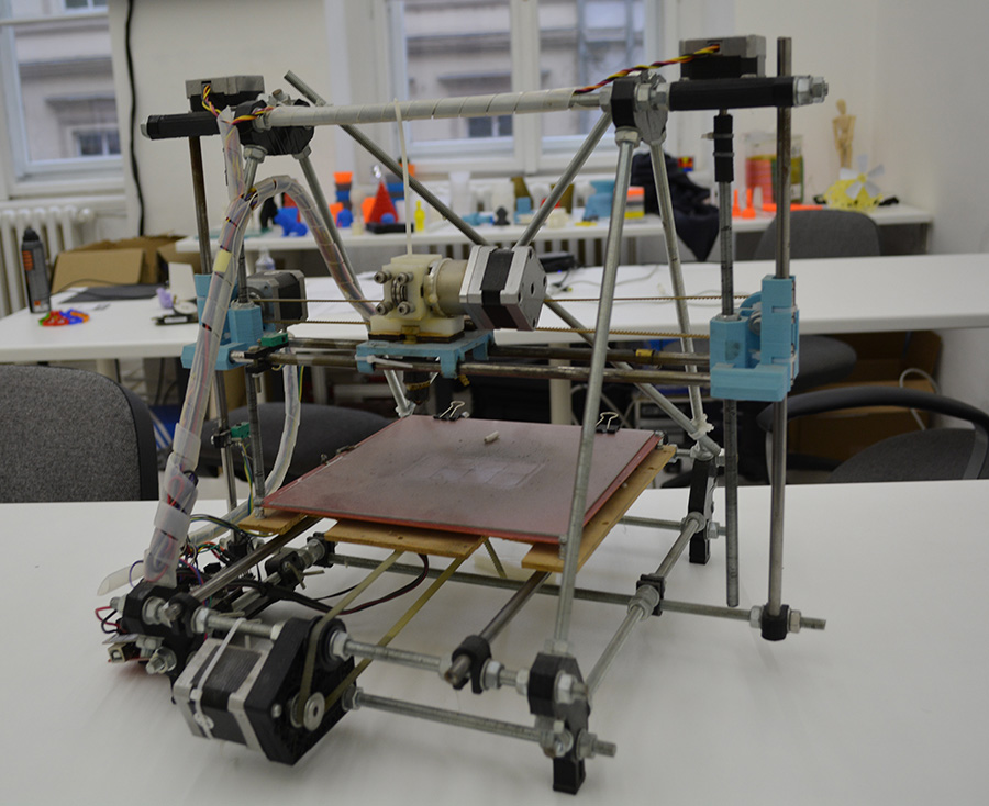
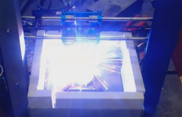
Whenever the question of metal 3D printers comes up, someone always chimes in that a MIG welder connected to a normal 3D printer would work great. A bit of research would tell this person that’s already been done, but some confirmation and replication is nice. A few students at TU Delft University strapped a welder to a normal, off-the-shelf 3D printer and made a few simple shapes.
This project builds on the work of [Joshua Pearce] et al. at Michigan Tech where an MIG welder and delta bot was used to lay down rather complex shapes on a metal plate substrate. The team at TU Delft used a cartesian bot – a Prusa i3 – for their replication because of the sheer mass of moving a metal build plate, firebricks, and welder around.
In the first few prints on their machine, the team was able to lay down enough metal to build a vertical wall. It’s not much, and to turn this into a finished part would require some machining, but these are only the beginning steps of what could become a legitimate way of creating metal parts. Video below.
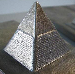
For years now, people have been trying to develop an affordable, RepRap-derived 3D printer that will create objects in metal. There has been a lot of work with crazy devices like high-powered lasers, and electron beams, but so far no one has yet developed a machine that can print metal objects easily, cheaply and safely. For The Hackaday Prize, [Sagar] is taking a different tack for his metal 3D printer: he’s extruding low temperature alloys just like a normal 3D printer would extrude plastic.
[Sagar]’s printer is pretty much a carbon copy of one of the many ‘plastic-only’ 3D printers out there, the only change being in the extruder and hot end. As a material, he’s using an alloy of 95.8% tin, 4% copper, and 0.2% silver in a 3mm diameter spool. This alloy melts at 235° C, about the same temperature as the ABS plastic these printers normally use.
The only real problems with this build are the extruder and nozzle. [Sagar] is milling his own nozzle and hot end out of stainless steel; a challenging bit of machining, but still within the realm of a hobbyist. He has some doubts about the RepRap derived plastic geared extruder being able to handle metal, so he’s also looking at designing a new version and milling that out of stainless as well.
It’s an awesome project, and we hope we’ll be seeing some updates to the project shortly. While a 3D printer that produces objects out of a low temperature alloy won’t be building rocket engines any time soon, it could be a great way to fabricate some reasonably high-strength parts at home.
The project featured in this post is an entry in The Hackaday Prize. Build something awesome and win a trip to space or hundreds of other prizes.
If you think about it, the RepRaps and other commercial 3D printers we have today are nothing like the printers that will be found in the workshops of the future. They’re more expensive than they need to be, and despite the RepRap project being around for a few years now, no one has cracked the nut of closed loop control yet. [mad hephaestus], [Alex], and [Will] over on the Hackaday Projects site are working on the future of 3D printing with the Servo Stock, a delta printer using servos and closed loop control to build a printer for about a quarter of the price as a traditional 3D printer.
The printer itself is a Kossel derivative that is highly modified to show off some interesting tech. Instead of steppers, the printer has three axes controlled by servos. On each axis is a small board containing a magnetic encoder, and a continuous rotation servo. With this setup, the guys are able to get 4096 steps per revolution with closed loop control that can drive the servo to with ±2 ticks.
The electronics and firmware are a clean sheet redesign of the usual 3D printer loadout. The motherboard uses a Pic32 running at 80MHz. Even the communication between the host and printer has been completely redesigned. Instead of Gcode, the team is using the Bowler protocol, a system of sending packets over serial, TCP/IP, or just about any other communications protocol you can think of.
Below is a video of the ServoStock interpreting Gcode on a computer and sending the codes and kinematics to the printer. It seems to work well, and using cheap servos and cut down electronics means this project might just be the first to break the $200 barrier for a ready to run 3D printer.
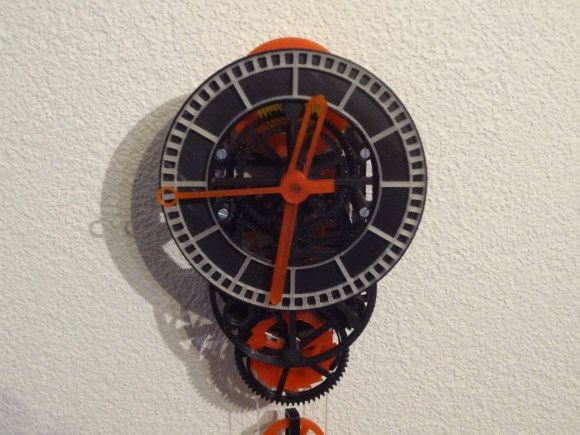
Many have tried, but [Christoph Laimer] has succeeded in designing a working, (relatively) accurate clock nearly completely from 3D printed parts. Every gear, pulley, wheel and hand of [Christoph’s] clock is printed. Only a few screws, axles, a weight, and a string are non-printed. Even the crank to wind the clock is a 3D printed part.
[Christoph] designed his clock in Blender. It took quite a bit of design work to create parts that would work and be printable. Even more work was involved in printing over 100 failed prototype parts.
One might think that [Christoph] is using the latest printers from the likes of Makerbot or Utimaker to achieve this feat. It turns out he’s using a discontinued Rapman 3.2 printer. Further proof that even “older” printers are capable of great things! [Christoph] does run his printer rather slowly. Printing a single gear with 0.125 mm layers and a 0.4 mm nozzle takes him 2 or 3 hours.
Mechanically, the clock is gravity powered with an anchor escapement. Rather than a pendulum, [Christoph] chose to use a balance wheel and hairspringassembly to govern the escapement. Even the spring is printed from standard PLA. The weight is suspended from a pulley block. The clock isn’t particularly efficient. 70cm of height will run the clock for only 2 hours.
[Christoph’s] clock has proven to be accurate to within 1/4 second per hour. He hasn’t provided temperature stability data – but being PLA, we’d suggest not getting it too hot!


 For years now, people have been trying to develop an affordable, RepRap-derived 3D printer that will create objects in metal. There has been a lot of work with crazy devices like high-powered lasers, and electron beams, but so far no one has yet developed a machine that can print metal objects easily, cheaply and safely. For The Hackaday Prize,
 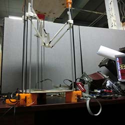 If you think about it, the RepRaps and other commercial 3D printers we have today are nothing like the printers that will be found in the workshops of the future. They’re more expensive than they need to be, and despite the RepRap project being around for a few years now, no one has cracked the nut of closed loop control yet. [mad hephaestus], [Alex], and [Will] over on the Hackaday Projects site are working on the future of 3D printing