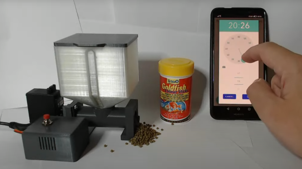
Sometimes daily tasks, like feeding pets, can feel like a real chore. To help with alleviate the mundane aspects of daily life, [Erik Berglund] has created an automatic fish feeder, complete with 3D print files, firmware, and an Android app for complete control over scheduling and feeding.
The mechanics of the fish feeder include a screw conveyor system that pushes the food pellets fed from a food store basin. The screw conveyor is driven by a Feetech FS5106R servo which provides enough force to overcome jamming that might occur with pellets getting stuck in the conveyor system. [Erik Berglund] writes that the system can dispense about 0.9 g/s and that it’s designed for granulated food, as flakes have problems because “their low density and large surface area tend to get them stuck in the throat of the hopper” — an issue that we’ve looked into previously.
[Erik Berglund] used [coberdas]’s fish feeder as the base, upgrading it with a better servo, adding a Raspberry Pi Zero W along with software for the Pi and an Android application to control the schedule of feedings. There’s also a DS1307 real time clock module to keep precision time and a push button for “manual” feeding. If you’re looking to follow along at home, you can find the Python scripts that run on the Pi and the source code for the Android application in their respective GitHub repositories.
Your [Bornhack] plans include leaving lemons in patterns as an info display. Your squirrel feeder needs to only dispense nuts when the squirrels deserve it. As promised last week, an intro to gating, feeding, and moving bulk material.
Gates
Bulk material flow needs control. Starting is easy, it’s stopping that’s hard.
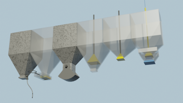
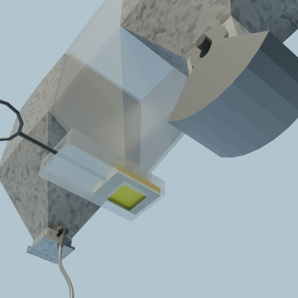
Dump Gate, Slide Gate, Clamshell Gate
If your need is just to dump out the entire contents of the bin, a dump gate works – a trapdoor with a latch. If you need to stop before emptying the bin, you can use a slide valve – a flat piece of material in a box that slides in and out. Friction from material bearing down on them causes large open/close forces. Material can jam between the flap and the housing when closing.
A variation is the clam shell gate — a section of a cylinder on arms that swings aside, like a crane’s grab. They tend to leak, but with the material’s weight against the hinge pin, they are easier to close with a high force against them.
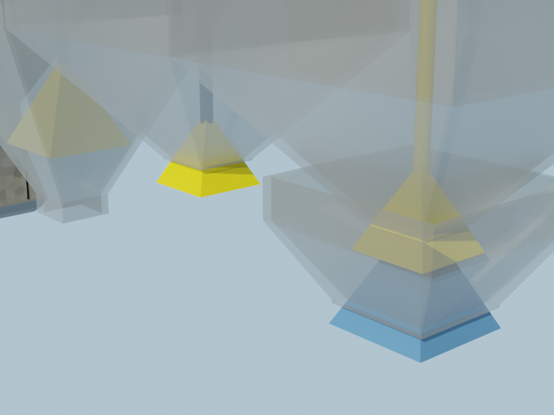
The upward bell gate, helps with in-bin flow pattern and seals well. Open by pulling from above or pushing from below, through the outlet. The material moving around the gate acts to improve the flow, and because the material at the lip is on an inclined surface, they tend to seal better. If it still has a leakage problem, a flexible lip can cure it.
A cone, suspended on a cable below the outlet of the hopper is a downward bell. Lowering the cable lets material flow between the outlet rim and the bell. When the cable is raised, if a lump sticks at one place the bell moves aside. The sealing surfaces are angles, so material rolls off. The bin is shallower and there’s no outlet pipe. This design ensures clearance so large particles don’t wedge against the wall as the bell closes.
Upward Bell, Downward Bell, Double Bell
Any of these gates would close just fine if not for the material in the bin. Double gates exploit this. The main bin has a normal gate and outlet. The outlet is below the lip of the much smaller, lower control bin. If the control bin fills, the main bin stops. The control bin has a gate larger than the main bin. Closing the main gate as far as it will go reduces flow through the control gate to a trickle. The control gate can now be fully closed, which fills the control bin and blocks the main outlet.
You might not want to share environments between bins. Maybe one has pressure, nasty chemicals, or hot gases. In that case, a rotary airlock gate is a paddle wheel apparatus in a close fitting housing. Material is metered out as it turns. A double gate also works (blast furnaces use double bells). If you need to meter a set amount, a sliding cavity like a grocery store bulk bin works. So does a rotary airlock.
Locomotive sander systems spread sand on the rails to increase traction. The sand is gated with a “sand trap”. A pipe supplies sand to a ‘valve’ with a sharp upward U bend. Of course this blocks. A compressed air line from a valve in the cab feeds into the upward end of the U bend. As long as air flows, the blockage is constantly cleared and sand flows. It’s collected and sent to the wheels.
Feeders
If you need a constant flow, independent of how much is in the bin, you need a feeder.
The rotary air lock can be a simple feeder. A conveyor feeder is a belt at the bottom of the bin. One side has a slight gap between bin and belt. Material covers the belt as high as the gap. A screw feeder is a helical screw at the bottom of the hopper, taking material off to the side. The screw needs a varying pitch, starting out slow and increasing, to let it fill gradually from all along the hopper. A vibratory feeder is a chute designed to arch, with a vibrator to make it flow anyway.
Any of these can have a poor pattern of feeding, taking from one place along it’s inlet. Fins and inserts in the bin can help – a doctor blade to regulate how deep the first couple inches of belt feed, or an anti-rathole type insert to keep mass flow going.
Conveyors
Unlike a feeder, a conveyor depends on whatever is feeding it to control the feed rate. Feeders are for controlling feed rate. Conveyors for moving stuff. A feeder will change it’s output when it’s speed changes. A conveyor may change how much is in each section (the ‘loading’) but the output is speed independent.
Screw conveyors should have a fixed pitch, and can be angled up to 45 degrees. Belts can be inclined up to the angle of repose of the material. These are best made with a slight ‘V’ in the belt so the material doesn’t roll off. Boards on the side also work, but introduce friction into the system as the material slides against them.
Don’t overlook skips — a bucket pulled up an incline. The front wheels run on tracks slightly narrower than the back wheels. Dip the inside tracks down at the end to dump.
Moving floors made of long strips will move a pile of material if actuated in the proper sequence. Picture the order as ‘123123123123’: shove 1 backwards suddenly, and the material above it will stay with the mass, do 2 and 3, then slowly move all forward. They also move solid objects, so many trucks have such floors.
Finally, you can always fluidize the material and blow it about with air or water, then remove the fluid at the other end. Think old time logging, with logs floated down the river.
Have fun hacking. We hope we’ve given you some options for dealing with walnuts.
Many of us have heard the name Archimedes’ screw — but not everyone knows the term screw conveyor. These folks (sadly, the videographer at [Breeze Media] doesn’t tell us their names, or the company name) has the process of building screw conveyors down to a fine art.
Screw conveyors are useful, but many folks shy away from them because they look hard to make. In this video, we see how it’s done. The crew in this video are doing it in metal for large equipment, but the same methods could be used in plastic sheet or paper on a small scale.
It starts with cutting washers and slitting radially. When they’re distorted into the final shape the hole will close up, so the hole is a bit larger than the pipe that forms the center. They’re then given a slight spiral (think a lock washer) by walloping with a sledgehammer. It works. The slit edges are welded together to make a ‘compressed’ spiral, and the end is welded to the pipe
Now for the ingenious bit. They have a tall gantry, just a couple of pipe poles with a crossbar, set up in the factory yard. Below it, they’ve drilled a well. The free end of the pipe goes down the well. The bottom of the spiral is clamped to a baseplate around the well. Next, the pipe is hoisted up to form the final shape. Finally, everything is welded in place.
In the video after the break, they’re making a screw feeder. It needs a lower pitch for the section under the hopper. So they clamp several turns, pull the main section out, weld it, then move the clamp and make the feeder section.
Hacks are partially art, and screws are visually interesting. This piggy bank has one. Put one in your next hack!