GPS Engagement Ring Box

gpsEngagementRingBox

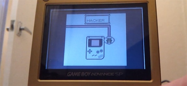
[James] got engaged recently, in part thanks to his clever GPS Engagement Ring Box, and he sent us a brief overview of how he brought this project to life. The exterior of the box is rather simple: one button and an LCD. Upon pressing the button, the LCD would indicate how far it needed to be taken to reach a pre-selected destination. After carrying it to the correct location, the box would open, revealing the ring (and a bit of electronics).

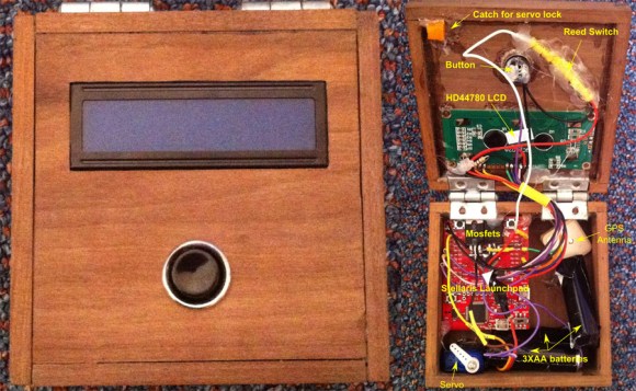
Inside is a GPS antenna and a Stellaris Launchpad, which are powered by three Energizer lithium batteries to ensure the box didn’t run out of juice during the walk. To keep the lid closed, [James] 3D printed a small latch and glued it to the top of the box, which is held in place by a micro servo. Once the box reaches its destination, the microcontroller tells the servo to swing out of the way, and the box can then open. As a failsafe, [James] added a reed switch to trigger an interrupt to open the box regardless of location. It seems this was a wise choice, because the GPS was a bit off and the box didn’t think it was in the correct place.

Swing by his blog for more information on the box’s construction and the wiring. We wish [James] the best and look forward seeing his future hacks; perhaps he’ll come up with some clever ones for the wedding like our friend Bill Porter.

Spoofing Pokemon Trades

[Adan] had an old Game Boy sitting around, and without anything better to do decided to investigate the link cable protocol with a microcontroller. He had a Stellaris Launchpad for the task, but initially had no project in mind. What he came up for this adventure in serial protocols is a first gen Pokemon trade spoofer that allows him to obtain pokemon without having two Game Boys, or for the weird ones out there, “friends.”

The Game Boy link protocol is extremely well documented (dead link, try Internet Archive), so getting data from the Game Boy to the Launchpad was as simple as a soldering up an old link cable connector to a piece of perf board. After figuring out the electronics, [Adan] looked at what happened when two Pokemon games tried to trade pokemon. When two Game Boys are linked, there are two in-game options: trade or battle. Looking at the data coming after the ‘trade’ option, [Adan] found something that could possibly be the data structure of the Pokemon being sent. He reverse-engineered this all by himself before discovering this is also  well documented.

Bringing everything together, [Adan] figured out how to trade non-existent Pokemon with a small dev board. Right now he’s only transmitting Pokemon that are hard-coded on the Launchpad, but it’s very possible to transmit the Pokemon values in real-time over USB.

Thanks [Dan] for sending this in, and no, we don’t know what’s up with the influx of Pokemon posts over the last week. Video of the spoof below.

Continue reading “Spoofing Pokemon Trades”

How To Configure Eclipse For The Stellaris Launchpad

eclipse-for-stellaris-launchpad

We’re partial to using gedit and a makefile for our AVR projects. But for the most part we don’t a debugger with those smaller chips. Now that we’re getting going with ARM processors we use debugging all the time and Eclipse is a great way to combine code writing, compiling, and debugging in one place. Sure, we could use one of TI’s provided IDEs (some of them are based on Eclipse), but we’d rather build our tools up ourselves. [Doragasu] is making this a snap with his Eclipse for Stellaris Launchpad tutorial.

He illustrates every step with a screenshot like the one seen above. Here he is including the driverlib from StellarisWare in the linking step. After all of the compiler and linker settings are just right all you need to do is make a copy of the template to start a new project. The final part of the setup configures lm4flash to write binaries to the chip, and configures OpenOCD for use when debugging.

[via Comments]