The simplest and easiest way to charge a battery with a solar panel is to connect the panel directly to the battery. Assuming the panel has a diode to prevent energy from flowing through it from the battery when there’s no sunlight. This is fairly common but not very efficient. [Debasish Dutta] has built a charge controller that addresses the inefficiencies of such a system though, and was able to implement maximum power point tracking using an Arduino.
Maximum power point tracking (MPPT) is a method that uses PWM and a special DC-DC converter to match the impedance of the solar panel to the battery. This means that more energy can be harvested from the panel than would otherwise be available. The circuit is placed in between the panel and the battery and regulates the output voltage of the panel so it matches the voltage on the battery more closely. [Debasish] reports that an efficiency gain of 30-40% can be made with this particular design.
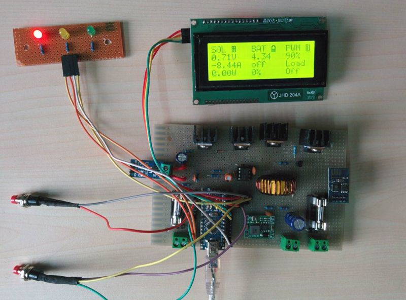
This device has a few bells and whistles as well, including the ability to log data over WiFi, an LCD display to report the status of the panel, battery, and controller, and can charge USB devices. This would be a great addition to any solar installation, especially if you’ve built one into your truck.
This is [Debasish]’s second entry to The Hackaday Prize. We covered his first one a few days ago. That means only one thing: start a project and start documenting it on hackaday.io


good idea. I will try it.
It’s not very useful in small setups, because the DC-DC converter has efficiency losses and the circuit uses power when the panels are not producing anything.
If you gain 40% theoretically, but your efficiency is 80% you’ve only got 12% left over after all, and with the parasitic consumption you’ll end up less than you started with.
easy enough to throw on a low power relay that only runs the whole circuit when power is coming in from the panel. That would have negligible parasitic losses, say 50-100mw.
I you want to use a relay to switch use a latching pulse relay one pulse on one pulse off so when the relay is on or off the relay draws zero
Bob
What if you miss a pulse?
In reply to Dax;
Post relay current monitoring
i always hate when they use the word special…its about the same as using the word magic…common this is hackday…give it up…
“This fairly common but not very efficient” – says who? I don’t know anyone who has hooked a solar panel directly to a battery, unless it was a tiny 10 watt or less panel.
The project itself looks decent though. It’s certainly something I’d consider reproducing. I just wish some HaD authors didn’t feel the need to spout nonsense when writing posts.
Having a diode in series loses you 1V – 1.7V from your solar panel, which ALWAYS means less efficient. By not having any electronics in line with the solar panel, you theoretically get the most power out of it. MPPT controllers use active electronics that don’t drop as much voltage across them as a traditional power diode approach, but they’re still less efficient than a direct connection.
AKA – Sez science ;P
I think you can use a FET and bias the gate with a resistor to source that way when there is now input the FET drops out but when you have an input the FET fully conducts so no drop in voltage
Bob
Do you have any examples (links)? I have seen that technique done, but I always assumed there would be a voltage drop due to the non-superconducting nature of a FET, so there should be a (small) but current dependent voltage drop across the FET. Also, if the bias is not high enough the FET won’t turn on fully.
If a FET or any transistor is used as a diode, there’s always a voltage drop equal to the treshold voltage of the device.
Here is one…
http://opend.co.za/hardware/200ds232/index.html
It also has an innovative feature where it switches the FET off briefly every so often and uses an inductive kick to determine current direction.
It isn’t just that. A true MPPT makes sure that the panel voltage/current set point is always at the maximum power point for the panel at any given time.
It also allows for charging in low light conditions when the panel voltage is actually less than the battery voltage.
For small solar setups (less than 200W) it often doesn’t make sense to use an MPPT, but for larger ones, it because a very big factor.
Well you are sort of right but also wrong. The reason it isn’t used in smaller setups is because it’s cheaper to use more solar cells. The cost of solar per watt, and space, becomes the factor that prevents more solar panels in large setups, so using an mppt charger will then produce more peak watts for the cost of the charger, rather than the high cost of how much it would be to get those extra watts from extra panels. Mppt chargers are fairly expensive to consider for a small setup, but relatively cheap compared to the price of 1000 watts extra for the cost of the charger.
No, while a direct connection loosed pretty much nothing in the connection, the resistive losses within the solar cells can be significant. MPPT allows the panel to operate with a higher output voltage than that needed for the batter charging but at a point where the current from the cell is not diminished. Note that clamping the cell voltage does not usefully increase the cells current capability above that available at the MPPT point of its output V-I curve.
typo:- batter = battery
I do all the time. 40Watts of panels directly to a 100Ah battery for field operations. Only thing between it is a diode on each so that the cells cant drain the battery when shadowed.
That is a nice project. I like the flowcharts in the gallery.
Mildly unreleated but to tip some people off: You can also use a Lipo Rider (pro) by seeedstudio if you need to charge a (lipo) battery from a solar cell and dont have to log the data with the ESP8266
http://i.imgur.com/Dh8jKVP.jpg
Just about every solar garden/walkway/security light has no charge controller, they just rely on the charging solar cell not being able to boil the battery dry, however, over time they do just that, or the battery is left so depleted long enough for it to die of it’s own accord..
I have an ex military 40W portable cell array, with inbuilt blocking diode, that I use with no controller to keep a parked vehicle battery topped up at festivals etc, or keep the caravan battery topped up. Not as efficient as it could be, but more than good enough, and for me, more importantly, electrically quiet! (No EMI/RFI)
Even with no controller, that has brought a car battery back from being unable to start the car (unable to even run the stereo or interior light!) To doing it easily in a few hours of bright sunlight here in the UK. (Friend forgot to turn off the beer cool-box when parked!.)
There are other MPPT algorithms, but P&O is one of the easier ones to implement in a single chip micro-controller. However, they can sometimes get “stuck the wrong side of the hill”, if the incident light level changes a lot in a short time, such as a day with blue sky and large clouds. I guess if you can “perturb and observe” fast enough, that might help. Or regular periodic scheduled resets…
The controller PWM power stage too, needs careful design in regards to conducted emissions, keep you circulating current loops physically small, and filter the input, as well as the output, else your solar array will radiate large amounts of the PWM frequency and harmonics etc, “upsetting the neighbors” (or making you a target for anti’tech drones!)
Overall with the UI and remote logging, nice job.
DJB
Interesting.
I would like to charge some batteries (maybe 1 lipo?) from either a 12V solar cell or 2 peltiers in series (about 4V, but it’s really unstable and voltage changes every second) and get stable 5V for USB charging from that battery.
What is the best approach? Can you please recommend me some circuits, buck/boost IC or anything?
http://en.wikipedia.org/wiki/Single-ended_primary-inductor_converter
SEPIC works when the input voltage fluctuates under and over the output.
Thanks a lot!
What is needed is a charge controller that can also switch to a boost converter when the solar panel voltage drops, that way you can still get a charge on cloudy days.
Indeed!. I looked over the schematic, but was a little puzzled there was no coil in there (might have missed it, low res jpg)[oh wait there is a fscking big coil on the photo, nvmd]. The fixation on lead acid is a bit stifling I think, LiFePO will last longer and weigh much less. LiPO batteries will hold even more charge per weight. One of the main obstacles for solar is the lack of efficiency when storing power. If you keep using old battery technology it will never improve.
The silly thing seems to me that all panels are still wired for 12V,
On the one hand you need to pull as much power from the panel, but on the other hand you need to limit the current and voltage that goes into the battery, and at the extra hand your neighbour lent you you wish to keep the voltage that goes into the house also stable. I wonder it this controller only handles one part, or does all three?
I love lead acid because it’s so easy to recycle the lead. AFAIK most other battery types are mostly just thrown away.
The poor efficiency of PbA batteries isn’t an issue when you use a large bank of them, because the current drain on each cell becomes small.
The larger problem is that the ESOI of lead batteries is just 2, which means it takes half as much energy to manufacture a new battery as can ever be stored in it. It completely defeats the point of using green energy, since the manufacture and recycling will put out just as much pollution if not more.
[Jelle] one thing I want to point out is [Debasish Dutta]’s location. India might be full to the brim with electronic geniuses, but much like my home, South Africa, batteries like LiFePo are ridiculously expensive. Ordering from ebay is even worst, because then you have to pay $10 import duties for a $1 item. In that case, Lead Acid starts to make sense because you can easily pick one up from a scrap yard. I mean, where in India do you find a motorcycle battery…..
I quite agree. It was only within the past fifteen years that here we’ve reached the point that such batteries are cheap enough for our designs. Prior to that it was indeed a motorcycle grade battery. Or the ones used on boats who are designed with deep charge and deep discharge cycles in mind. In fact there’s an article online regarding how Phil Karn the fellow behind KA9Q (software not his Ham call letters) arranged for solar delivered services to his home in California. its dated now because some of the items he used are sadly only available on eBay. But the pretense behind it makes for good reading.
Here we can find and typically do make use of the gadgetry you are thinking of, but the excellent ideas suggested by our author make up for what is and sadly isn’t available there.
Hey you can see the Schematic in PDF format
http://www.instructables.com/files/orig/FQO/PS5A/I6B1RI4U/FQOPS5AI6B1RI4U.pdf
Where’s the rest of the schematic? i.e. how it’s connected to the arduino nano?
And where’s the source code?
lead acid is better for stationary power setups because weight and volume aren’t as much as issue, lead is cheap as crap compared to lithium, and lead is far more tolerant to abuse than lithium.
It isn’t more tolerant – it’s actually quite fickle and it’s easy to irreversibly damage lead acid batteries.
They don’t like hot, they don’t like cold, they don’t like high currents, they don’t like low currents (sulfation), they don’t like deep discharge, they don’t like continuous trickle charge… everything you do with them hurts them, which is why lead acid batteries are only good for about 500 cycles.
The results of mishandling them are just less spectacular. You can boil them, stab them, short-circuit them and the worst you get is a bit of steam.
That sounds good so when will it be designed then?
Bob
That would improve this project, and, would then see it as a useful charger for solar panels on a narrow boat which is often off grid.
This would do well I assume as a Kick-Starter proj
I am also interested for Kick Starter.
But before going to start .I have to optimize everything.
Need some help from the experts, for hardware and software optimization.
I am requested to all the experts to look in to my hardware and software.
Thanks
You need to provide full schematics, including the arduino connections as well as your source (i.e. github link) in order for people to look at it.
From what I see so far, you could try without the mosfet driver – compared to other MCUs (PIC, ARM), the AVR has high drive strength, and at the frequencies you are dealing with, the switching speed should be adequate.
I don’t see how you control the charging. I see some scope screen shots that appear to show PWM output of ~16V. When a standard flooded lead-acid cell reaches a full charge, over 14.4V is likely to boil off the electrolyte. Even in cool temperatures (i.e. 5C), 15V is enough to ruin the battery. In a hot climate like India, you risk damaging the battery with anything over 14V.
There’s plenty of sites that explain. Here’s a page I recommend by fellow Canadian Isidor Buchmann.
http://batteryuniversity.com/learn/article/charging_the_lead_acid_battery
http://www.linear.com/product/LT3652 or the http://www.linear.com/product/LTM8062 are nice for small applications. I built one using the latter to charge a 2-cell (in series, with load balancer) 10Ah LiFePO pack with a 10W solar panel. A http://www.maximintegrated.com/en/products/power/switching-regulators/MAX1626.html makes 5V for a USB charging port. A comparator with a 1.5V hysteresis puts the MAX1626 in shutdown when the battery voltage drops below 5V. Works like a charm, but it isn’t really a design, just an application of Linear’s design.
similar to “Arduino Peak Power Tracker Solar Charger”
http://web.archive.org/web/20130430163911/http://www.timnolan.com/index.php?page=arduino-ppt-solar-charger
I think every arduino based mppt charge controller design I’ve seen are all based on Tim Nolans original design, yet rarely is he given any credit. Although, his site being down might be a sign that his design has given him a little too much attention.
I would leave off the wifi since it uses power. BLE uses a lot less power.
That and a micro controller controlling it that goes into sleep mode for most of its operation time. Probably can set it to trigger when something goes wrong or on a timer. The setup will pull so little current, it would be like it wasn’t even in.
The full project can also be found here
http://www.instructables.com/id/ARDUINO-SOLAR-CHARGE-CONTROLLER-Version-30/
Guys, diode era for solar panels is over. Google for “active solar bypass diode” (from TI as well as from Microsemi – both are giving free samples). 26mV forward voltage drop is really impressive.
Thanks for heads up
Here is a quote
Conclusions and outlook
Smart bypass diodes approach “ideal diode” behavior with an order of magnitude performance increase. High-performance panels and integrated electronics will be the first adopters of this new technology, before it will be used in the mass market. The smart bypass diode is the first type of electronic circuitry used in PV panels, opening the path for additional electronic solutions to improve energy yield, new features and services. The energy advantages of the smart bypass diode are noticeable and offer potential for a growing array of opportunities in other markets.
I’m wondering when they will build MPPT directly into the panels anyway . Logical place for it to be.
that exists already in the form of grid tie panels with mppt and inverters built in. for everything else, it’s often better to have a separate mppt/charge controller for better efficiency. an example of this would be a 150v array located 100ft from a 48v battery bank. it’s more efficient to run 150v a long distance than it is to run 48v.
I’m actually surprised there aren’t people trying to get at least 80% on controller designs.. I think I read once most manufactures only get 60% at best over basic diode design loss.. Solar isn’t going away any time soon so it’s not a wasted effort by no means..
Well it might be useful if the guy puts the code up somewhere. Useless without it
The code can be download from the link bellow.
http://www.instructables.com/id/ARDUINO-SOLAR-CHARGE-CONTROLLER-Version-30/step39/Software-and-Algorithm/
according to google that page was there before it was on hackaday..
I spent time writing this down and clearing it up as best as possible, so please if you start reading it , finish it at some time, whenever possible. Thanks, before you jump (out of your chair XD, which is NOT the intention !!!):
Standard, generic or common by definition MPPT device as idea & design is obsolete. And I just got eyesight of *unio – – – – this thing does not have any, I mean any chance to be MODERN MPPT. Simply because of its MCU and I will stop there, but we can go on with what are the conditions on PVPP sites or even HOME PV System. And MPPT in common is an Obsolete thing – [100% – 1% exceptions] YES, but:
Good for Experience – YES!
Good for Advancing Skills – hell yes!
Gather more and more knowledge on Analog & Digital interaction – YEEES!
+ Metering Values work – ABSOLUTELY YES!
But yet again Design that is Applicable in REAL WORLD MODERN SYSTEMS – Sorry, but no.
MPPT in standard form is obsolete, you need at least few basic DSP procedures, simple very, but still … fixed point math – ok , but ATtiny gives you no chance at this, ATMega – depends on features.
For 3rd world or underdeveloped countries – it may be applicable design, but if you invest there you would want the OPTIMUM if not the “best” never possible solution. And this will be NATURAL, because you have harsh conditions, low number if any at all power suppliers, you’ll be low on storage options, etc. If you have to power a village in Europe you will have 1 PVPP on that Village OR even more + 1 or more Stable Power suppliers & infrastructure :| So….
It’s absolutely A GREAT HACK/MAKER thing OR student’s research paper, but with *unio stuff can’t be applicable as MODERN applicable. Study, develop – perhaps, it depends, in most cases – it can get you going. But to build an actual design that LATER ON can be ADDOPTED into ACTUAL PRODUCT or REPRODUCED by other HACK/MAKERS and use on REAL PV systems … hmmm well I’m serious – No, if no exception occurs.
And before you JUMP out of your seat – If I have provoked that at all and not only curse words :X; please channel that energy into getting to USE the MCU on(the)board the –unio in C w/o more than 1 , tops 2 abstraction layers, i.e. w/o the –unio dev env. HAL is acceptable for such device, not much of Real-time constrains, although you will have some, but no critical timeframes or moments for reaction. AT worst you will lose PV modules performance or waste a bit of life over Storage system (whatever it may be). It’s just absurd for modern stuff OS/SW like –uino.
Just a fresh example from last month: MBED is promoted as LOW POWER capable OS. Compared to Bare-metal Device MBED will be 1.4-2+ X (times) more hungry for power consumption, simply because it has so many instructions coming from its abstraction layers (HAL & SW ones). MBED for me is Advanced –unio, perhaps now very advanced, but still the roots is the same. And the result you will get is a very different thing than something you can actually sell w/o some crazy PR stunt or Hype.
So Dude/Man – get into learning C and not that –unio crap IDE; so you can use your ATTiny/ATMega/etc. to its fullest (1) and (2) have real control & power over your Device/MCU/Board :)
The above all, but especially this one sentence / line is 100% personal opinion driven by facts & my experience + I’m a bit more direct than I should and still I think this is the right way given that people just worship –unio –pi’s and so on. And those are overpriced, low performing, closed devices (at best they open something after so many clones came out) and in the END you do not have Engineering Skills or Programming skills or whatever skills in general or at actual level – you only will have truly specific skills at –uino IDE & -uino Abstraction LAYER Libraries, etc.
If I get 1 student or Maker that work on C w/ STM32F4 (cortex-M4) and put him on SAM4S (cortex-M4) he will manage very quickly because below is CMSIS + HAL (abstraction – yes , but of only 1 level, tops 2).
And I DO HOPE YOU WANT TO NOT ONLY HACK/MAKE but to also IMPACT The World we live in?!.
NOTICE: This Project does NOT work. It’s a FAKE.
You will loose Your Money and Energy.