Non-planar layer Fused Deposition Modeling (FDM) is any form of fused deposition modeling where the 3D printed layers aren’t flat or of uniform thickness. For example, if you’re using mesh bed leveling on your 3D printer, you are already using non-planar layer FDM. But why stop at compensating for curved build plates? Non-planar layer FDM has more applications and there are quite a few projects out there exploring the possibilities. In this article, we are going to have a look at what the trick yields for us.
Smooth, Curved Surfaces
Non-planar-layer FDM allows for smooth, curved surfaces, which otherwise would show the typical staircase of discrete layers. Usually, I’m relying heavily on sand paper and spray filler to upgrade my 3D prints to Class-A, and I’ve been quite surprised by how smooth the non-planar test prints came out directly from the machine:


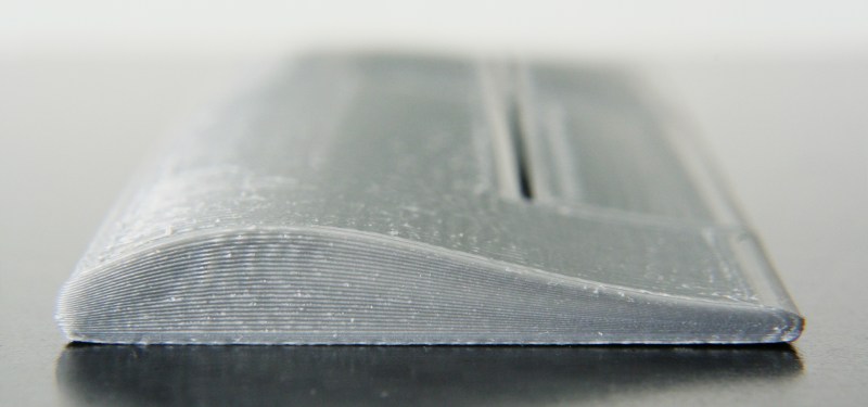
While the discrete layers aren’t always a problem when printing functional, mechanical parts, there may be applications where this comes in quite handy. The lack of discrete layers gives the models a nice look that requires no further smoothing, which may be helpful in design applications. The smooth surfaces may also help 3D printing aerodynamic models, like the airplane wing from the header photo:


Strengthened Parts
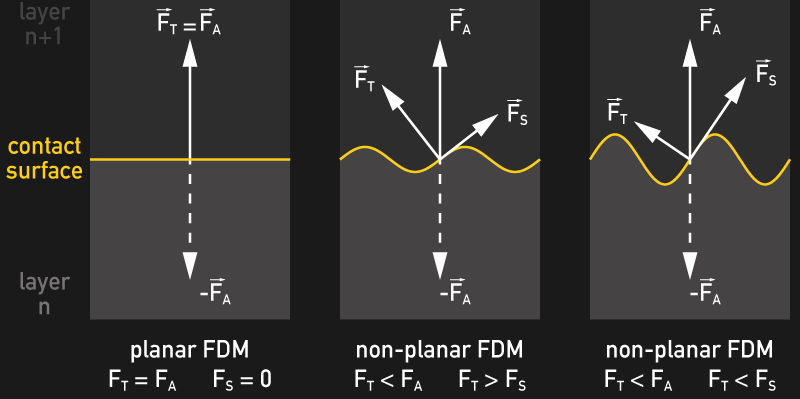
Non-planar printed parts seem to be stronger than their planar counterparts. You may be skeptical about this — although the varying orientation of the contact surfaces between layers could lead to a more uniform resistance to tensile stress. Planar printed FDM parts are typically less resistant to tensile stress along the build direction axis than they are along the other two dimensions, which can lead to delamination. Interlocking, non-planar layers can distribute tensile forces into a compound of tensile and shearing forces, with the latter being a particular strength of FDM printed parts. The graphic shows how the shearing component FS increases with increased displacement:
By adding transitions between displaced layers and compensating for the variable layer height, it is also possible to treat only certain portions of a 3D printed part, while leaving other parts entirely untouched. The following example print features a flat top and bottom, only the layers in between have been gradually displaced.


The slight wave in the above example may not exhaust the effect entirely. Unfortunately, my printer currently does not feature a very pointy nozzle, which limits its capability of printing steep curves. To make it easier to spot the displacement, I changed the material color mid-print. Any strengthening effect will certainly only be as good as the individual implementation, and eventually: Until this has been verified through measurement, I’d rather not stress this theoretical argument for non-planar layer FDM too much.
Structured Surfaces
Just like a tree stump reveals the annual rings of the tree, 3D printed objects also show signs of their formation process through the typical rippled structure along their outer shells. Objects printed in a planar fashion typically also show tool paths of infill and perimeters on their top layers. Non-planar layers allow you to add additional textures to the flat top surfaces of your prints, which may be especially interesting in custom design applications. The cube below has been printed using a 2D-sinusoidial displacement pattern.


These textures occur similarly to the mentioned tree-rings. Flat top layers of non-planar printed objects represent a cross-section through the displacement pattern, which results in interesting patterns by itself. It’s up to the individual application and taste if the creation of these patterns is desirable, yet I happen to find them quite beautiful.
Hands-On
Ideally, non-planar 3D printing is done using a somewhat pointy nozzle, as flat nozzles tend to dig into the previously printed material and easily get entangled in infill structures. Generally, a pointy nozzle allows for steeper printing angles, although you always need to make sure that no other parts of the nozzle or print-head are getting in the way. Especially fan mounts or ducts are prone to collide with parts of the print. I’m using an E3Dv6 hotend and nozzle for the examples in this post, although there are probably better solutions out there. In particular, the Merlin hotend features a very fine and pointy nozzle, with the only thing that could get into the way being the heater block.


The non-planar tool paths require a lot of action on the Z-axis, now is the time to add some fresh grease to its mechanics. Depending on how fast your Z-axis can move, you may also readjust its maximum speed and jerk settings in the firmware.
Using the template code of the G-code post-processing article last week, I put together a little script that lets you generate non-planar G-code on the fly using Slic3r. You can obtain the script from its GitHub repository, which also contains detailed instructions on how to use it. It also comes with several examples: The first three examples are the cube I used for the illustrations in this post, along with the same sinusoidal displacement function. The fourth example is the airplane wing model from the title graphic. The wing is based on a flat design that has been displaced to obtain the aerodynamic shape.


After exporting the G-code of this rather unspectacular design from Slic3r, which also pushes it through the post-processing script for displacement, the wing takes on its final shape. Due to the thin shells this method allows, it is very light. Still, it’s certainly not safe to fly and meant purely to illustrate the technique:


I printed the above G-code on a Prusa i3, using a 0.4 mm E3Dv6 nozzle. Even though this nozzle is not very pointy, the wing turned out quite well. Due to the suboptimal nozzle geometry, the top-side features shallow, regular grooves.


I hope you enjoyed this little excursion into off-track 3D printing. Check out the script and share your results, opinions and ideas with us in the comments!


Really cool results, I have always wondered why this isn’t more common. I mean for CNC milling this type of 3d movement is commonplace, not sure why this it not yet mainstream for 3d printers.
Thanks! Indeed!
Agreed – these are great results. I think the reason that it isn’t more common is that it is complicated. It isn’t impossible, as shown by great work like this. Some of the reason that this is complicated are the same reasons it is complicated in milling:
1) Some of the assumptions we don’t think about in printing are complicated. How do you want to the local plane of the print oriented? Tangent to the surface and linearly distributed between the planes on both sides? Something else? What is something else?
2) When the slope of the printing planes get steep, then you have clearance issues. This begs the question of whether a 5 axis printer is needed. It doesn’t really make sense until you do things like this article shows.
3) 5 axis milling CAM is complicated. The printer world is used to “set some parameters and the slicer takes it from there”. 5 axis milling CAM is complicated in comparison. Again, it’s complicated, not impossible…
Good point, this would only work for fairly shallow angles unless you had 5 axis just because the nozzle has to point somewhat normal to the surface it is printing on for practical reasons. But still – if limited to shallow angles it is a powerful technique. Even if the in-fill was completeley traditional 3d printing, if you can apply 2-3 shell layers that are smooth and continuous fillaments, it would vastly improve print finish without requiring small z-step. This would speed up 3d printing nice models quite a bit I would think.
I was reading through and accidentally clicked the report button. Would it hurt to have a simple “Are you sure?” pop-up or similar?
I SUSPECT that CNC has simply had a longer run of experimentation.
Really cool! I’m wondering how fast objects can be printed using this method. The Z axis is typically really slow.
Not for Delta style printers! If I wasn’t traveling this weekend I’d have just found my plans,I have two Rostock printers to try this on. E3D hotends, but the I have a.25 mm tip (smaller than the other nozzles) that would make for some fun comparisons.
Err.. it’s obviously smaller than larger nozzles, I meant to say it’s more pointy than other nozzles? Ugh there’s gotta be a better word for that outer diameter to bore size area.
I think the more important part is the thickness around the nozzle orifice and the E3D style nozzles aren’t that great. Merlin style nozzles work the best for this kind of use. Micro-Swiss offers plenty of good nozzles with only a thin edge around the oriface and I think they’ll work pretty well. Incidentally, I think the Micro-Swiss style nozzle for E3D works better than normal E3D style nozzles on PETG because there’s less risk of “plowing”. I don’t understand why E3D thought they needed such a large perimeter around the orifice, it’s a lot more than needed to help flatten a layer even assuming planar layers.
I am eager to hear your results, i might try it with mine setup – v6 with 0,25 nozzle on kossel
The prints I did for the post went through pretty fast. As long as you don’t run this two-motors-one-driver z-axis the speed won’t be much of an issue.
with the tool path being visible in the end result, it becomes important what the tool path ends up being.
the groves in the wing going fore to aft are not a problem (and may even be a good thing), but if they went side to side it would be a very bad thing.
I can’t help but think that even with a pointy nozzle it would be moving into the very same material it is placing when moving down a slope?
But nice technique!
I think given the fact it’s following the layer below it, the net effect isn’t a huge deal. A slicer could allow compensation to correct that effect, I expect it’s a matter of further development if there’s interest.
You can also vary the layer thickness as the nozzle travels on earlier layers to start a curve in the z axis.
One thing you could do is tell it to only to go “uphill” when routing the 3d layers, might help or it might hurt adhesion to layers below.
Great idea! Don’t think it would hurt the layer adhesion, but it might create a seam on the turning points.
Awesome Moritz great idea and work!
It looks like a very promising technique, THANK YOU!
Wonderful! Great work!
Hey Moritz, nice writeup!
I’m the developer of Bread, an open source slicer which supports nonplanar layers with arbitrary shapes. It takes a second mesh representing the layer shape as input. You can find it here if you’re interested: https://github.com/nick-parker/bread
I performed some mechanical testing on parts printed with various curved profiles two years ago, and they don’t actually display improved strength in Z axis tension. I wasn’t able to effectively test shear strength at the lab I was in back then, but I think it may be more interesting.
The angle between the surface of the previous layer and the nozzle is inversely proportional to the adhesion strength between those layers. This is because as you tilt the disk of the nozzle, its trailing edge changes from a constant height to a parabolic profile across the width of the extrusion. That parabolic profile compresses the bead less effectively, and as a result Z tension strength is independent of layer curvature to within about 5%.
Hey Nick! I’ve seen Bread, it’s really cool! I’d really love to see those test results, is there a possibility I could look into these? It’s really a critical question for projects like 3D printed cars, like the ones at Local Motors. Anyways, keep up the good work! Thanks!
As a CNC machinist, we used Ball End mills for 3D profiling on a 3 axis machine because we are removing material, even if it’s .020 thousandths at a time, but that doesn’t work for a 3 axis “Printer”. 4 or 5 axis would be a must in order to keep the nozzle perpendicular to the surface to lay the plastic bead down correctly. Unless someone can come up with a way to emulate the Ball End Mill tool, maybe a movable hotend or something? But that would require gymnastics to not break or bind the filament travel. Good post.
I had this exact thought last week – I’m VERY eager to try this on a very specific problem for a customer (fortunately I’m already using Slic3r!)
THANK YOU!
Thanks for sharing this development work, I believe it is the next great innovation to improving the performance of parts made by extrusion deposition machines.
Take a delta printer, add 3 more columns to create a full hexapod (6dof). This would be capable of tilting the head in all required directions, as well as twisting the head. No obvious need for that extra dof now, but someone might have some novel use for it?
Finally! I’ve spent so long wondering why my 3D printer can’t do stuff like print curved top layers to render a dome, instead of ugly stair-stepped layers, despite the fact that it’s like basic CNC pathing… I couldn’t find any examples. Now finally, something even cooler than I’d imagined. :D
Awesome work! Thanks for sharing. Which i3 kit are you using?
Thanks. It’s a “Proosha IIIo”, my reworked i3 rework fork: https://goo.gl/f3WNqF
First good work! I have been thinking about this for a long while.
One of my ideas that uses the same principle but is less demanding and “weaving/braiding” some “construction layers” for the infill.
The layer build up is made of a first set of parallel strings, Then a second layer 90 degrees from the first one that curves in the Z-axis between the first layer strings. The third layer then inter locks the second layer by filling the valleys on the second layer. That’s the basic “Constructional layer”. The sequence then just starts over rotated for example 120 degrees to make an new interlocking Constrution layer.
The principle uses tree layers but the construction layers are just two layers in height.
Hmm. Would be nice if we could abuse something like the Fusion 360 CAM module to make these non planar tool paths. I’ve only used F360 for modelling and sliced these models in S3D for printing. Maybe someone who knows the F360 CAM module a bit better could tell us if it would be possible to generate non planar toolpaths for additive manufacture? Or do we have to petition for Autodesk to actually develop an extension into F360?
I have used it a little bit, you could create a small pointy endmill with geometry matching your extruder, then create 3d toolpaths that follow the outer contours of your part. You would manually have to go in and massage the g-code, but in general the tool paths should work. This would also only really work as a top “icing” layer, Fusion 360 isn’t going to be good at creating in-fill tool paths.
That gets me thinking, as long as you generate G-code that mills a mold for your 3D model, you might actually use that G-code without too many modifications. Just flip it over and add the extrusion. But anyways, Slic3r does this extremely well. Just requires a script or two and you can print virtually anything.
Well now I need to purchase a printer…
Hey everybody! Thanks for all your ideas and feedback. You might be happy to hear that this might become an actual feature in Slic3r itself: https://github.com/alexrj/Slic3r/issues/3442
Really nice tests and write up…!
I didn’t came further than a plugin for Cura in 2013: http://www.youmagine.com/designs/printing-in-3-dimensions-finally
(and later some more experiments http://www.youmagine.com/designs/printing-in-3-dimensions-part-2)
back at the time the people I showed it thought I was using a 6 axis robot for that… : )
Looking forward for even more applications…
cheers / joris
http://www.rooiejoris.nl
Too many issues to account for in a 3Dprinting using filament in room temperature normal atmosphere, contamination of the interlayer contact bonding surfaces with various gas impurities and why not dust and other particles are taking the 3D printing with this method into the world of objects that cannot be trusted in certain applications, like in the wing example, you might get a neat surface, perfect interior cavities, light output, but would you trust such a printed wing on your microlight airplane with you at commands at 300 feet above the ground? Maybe with an additional metal structure inside the resistance can be improved, but than again, if you go through the trouble of making the ribs and beams of metal, isn’t it better to simply use cloth or Al sheet or this ply just like the others to cover the wing?
Why am I saying this? Simply because although for now the 3D printing made huge steps into reality passing from highly expensive machines to open source dirty cheap models nowadays, which is awesome, at least for me is awesome, we still cannot really print functional objects we can rely on for daily use in mechanical stress environments, but rather static useful objects such as a mug or a vase, or a statical example of no mechanical use for others, thus if you want to print up a new body for your car… it might come up sleek and cozy, but I think you would not drive it on a motorway traffic with your print body, just in case some accident happen, you are not safe in there.
I love the idea of non planner layer printing myself even if done as a compromise with planner layer core and non planner icing of the finished surface (to speed up the print or increase the strength or else) and I am glad the 3D amateur printing world has caught up with the dedicated industry dinosaurs tot the point where we really look into 5 axis printing ways like CNC milling machines do, that is more than awesome, but to top up the cake I would add a cherry, not mine but sweet the same, we need to look into other handy materials to make things printed usable in the real world not only as a static example, but as working parts, and here it comes the chance of open source thinking of thousands of independent amateurs that is far bigger than a laboratory locked secretive team paid to squeeze their heads, take it as a challenge if you will, I am in it for a while now, compete me, beat me on the finish line, doesn’t matter, just come up with something that makes sense.
Moritz,
Your code is very nicely laid out. It opens up possibilities to do all sorts of things.
I have made a rather terrible hack which distinguishes infill from perimeters by checking the feedrate and comparing with $parameters{“infill_speed”} (exposed by Slic3r). By creating a XY map of z-regions which are infill only, I can dynamically set wave_in and wave_out parameters across the object. This makes the infill wavy but perimeters straight, including holes, etc., with dynamic damping as the infill nears the perimeters. Caveat: I have not yet tried to print anything. Pictures: http://www.freecaine.org/~daniel/3d-nonplanar/
Woah, just came back here to find your comment. That’s some amazing stuff. I have to read into your writeup more, but it looks promising. Cool idea with the map. The script is prepared to read verbose output from Slic3r. If turn on verbose mode there, it’ll tell you right away which movea are perimeters. Nevertheless, awesome stuff!
This is a really good article! i have read other articles in this website and are awesome too!. I learned a lot about 3d printing here. Its good to know when printing this basic knowledge.