The Flexible Permanence Of Copper Tape Circuits

Somewhere between shoving components into a breadboard temporarily and committing them to a piece of protoboard or a PCB lies the copper tape method. This flexible Manhattan-style method of circuitry formed the basis for [Bunnie Huang]’s Chibitronics startup, and has since inspired many to stop etching boards and start fetching hoards of copper tape.
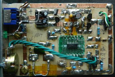
[Hales] hit the ground running when he learned about this method, and has made many a copper tape circuit in the last year or so. He offers several nice tips on his site that speak from experience with this method, and he’ll even show you how to easily work an SMD breakout board into the mix.

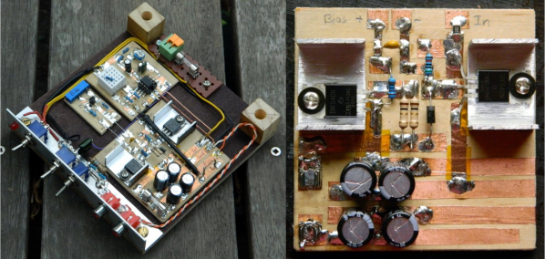
Generally speaking, [Hales] prefers plywood as the substrate to paper or cardboard for durability. He starts by drawing out the circuit and planning where all the tape traces will go and how wide they need to be. Then he lays out copper traces and pads, rubs the tape against the substrate to make it adhere strongly, and reinforces joints and laps with solder before adding the components. As you can see, copper tape circuits can get pretty complicated if you use Kapton tape as insulation between stacked layers of traces.

Copper and Kapton (polyimide) tape are just two of the many useful tapes you may not be aware of. Stick with us a moment and check out [Nava Whiteford]’s exploration of various adhesive marvels.

Oscilloscope Mod For The Blues

Roughly 8% of males and 0.6% of females are red-green color blind, and yet many common oscilloscopes use yellow and green for the traces for their two-channel readouts. Since [Roberto Barrios] is afflicted by deuteranopia, a specific form of red-green colorblindness that makes differentiating between yellow and green hard, if not impossible, he got to work hacking his Agilent oscilloscope to make it more colorblind friendly.

Starting with a tip from [Mike] from the EEVblog forums, [Roberto Barrios] set out to rewire the LCD interface and swap the red and green signals. That way yellow will turn bluish (red component replaced by blue) and it could be seen as “very different now” from the green trace on the readouts. Sounds simple right? Well, slight issue: the 0.5 mm pitch of the connector. He did not want to design a PCB and wait a few weeks to receive it, so he decided on using 0.1 mm wires held together with Kapton tape to route each signal individually from one connector to the other. After an hour under the microscope, it was done. And boy, his work is impressive, go check it out.

Voila! It worked splendidly. Now [Roberto Barrios] can use his scope. And, the stock UI is mostly grey or white, so swapping the red and blue channels did not change much the appearance of the interface. Moreover, the switch had a small unintentional bonus, the loading screen is much cooler now with an edgy red sky. Further, [Roberto Barrios] “would not be [himself] if [he] could resist changing the CH1 button backlight LED to blue, to match the new trace color. So, no [he] couldn’t.”

This was a well done and very functional oscilloscope mod, but if you need more frivolity in your life, fear not: we’ve got your back with real-time Quake played on an oscilloscope.

Kapton Tape Aids In Drag Soldering Surface Mount Parts

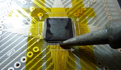
Drag soldering works exactly as its name implies, by dragging a bead of solder across fine-pitch pins you can quickly solder an entire row. The method relies on clean joints, so liquid solder flux is often used to make sure there is good flow. But if you’re drag soldering on boards that you’ve etched yourself the solder can sometimes run down the trace, rather than staying where you want it. Professionally manufactured boards don’t have this problem since they have solder mask covering the copper that doesn’t need soldering. [Ahmad Tabbouch] has a method that uses Kapton tape to act as a temporary solder mask on diy boards.

The process involves several steps. First, three strips are place horizontally across the board, leaving just a portion of the upper and lower pads exposed. Those pads are then tinned with solder, and a light touch with an X-acto knife is then used to score the tape covering the vertical rows of pads. Once the waste as been removed, two more strips are added and those rows are tinned. From there the chip is placed and soldered as we’ve seen before; first tacked in place, then fluxed, and finally drag soldered to complete the connections. This achieves a crisp and clean connection, presumably without the need to clean up your solder mess with solder wick.

Kapton tape resists heat, making it perfect for this process. We’ve also seen it used on hot beds for 3D printers, and as a smoothing surface for sliding mechanisms.

[via Dangerous Prototypes]