Pick and place reels

Pick And Place Hack Chat Reveals Assembly Secrets

These days we’ve got powerful free tools to do CAD and circuit design, cheap desktop 3D printers that can knock out bespoke enclosures, and convenient services that will spin up a stack of your PCBs and send them hurtling towards your front door for far less than anyone could have imagined. In short, if you want to build your own professional-looking gadgets, the only limit is your time and ambition. Well, assuming you only want to build a few of them, anyway.

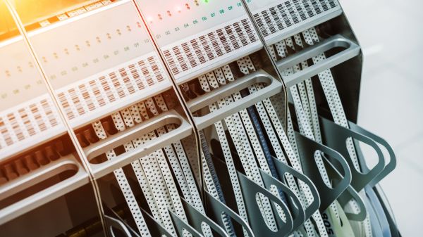
Once you start adding some zeros to the number of units you’re looking to produce, hand assembling PCBs quickly becomes a non-starter. Enter the pick and place machine. This wonder of modern technology can drop all those microscopic components on your board in a fraction of the time it would take a human, and never needs to take a bathroom break. This week Chris Denney stopped by the Hack Chat to talk about these incredible machines and all the minutiae of turning your circuit board design into a finished product.

Chris is the Chief Technology Officer (CTO) of Worthington Assembly, a quick turn electronics manufacturer in South Deerfield, Massachusetts that has been building and shipping custom circuit boards since 1974. He knows a thing or two about PCB production, and looking to help junior and mid-level engineers create easier to manufacture designs, he started the “Pick, Place, Podcast” when COVID hit and in-person tours of the facility were no longer possible. Now he says he can tell when a board comes from a regular listener by how many of his tips make it into the design.

So what should you be doing to make sure your board assembly goes as smoothly as possible? Chris says a lot of it is pretty common sense stuff, like including clear polarity indicators, having a legible silkscreen, and the use of fiducial markers. But some of the tips might come as something of a surprise, such as his advice to stick with the classic green solder mask. While modern board houses might let you select from a rainbow of colors, the fact is that green is what most equipment has been historically designed to work with.

That black PCB might look slick, but can confuse older pick and place machines or conveyors which were designed with the reflectivity of the classic green PCB in mind. It also makes automated optical inspection (AOI) much more difficult, especially with smaller component packages. That said, other colors such as white and red are less of a problem and often just require some fine tuning of the equipment.

He also pulled back the curtain a bit on how the contract manufacturing (CM) world works. While many might have the impression that the PCB game has moved overseas, Chris says orders of less than 10,000 units are still largely handheld by domestic CMs to minimize turnaround time. He also notes that many assembly houses are supported almost entirely by a few key accounts, so while they may be juggling 50 customers, there’s usually just two or three “big fish” that provide 80% of their business. With such a tight-knit group, he cautions CMs can be a bit selective; so if a customer is difficult to work with they can easily find themselves on the short end of the stick.

While the Hack Chat is officially only scheduled for an hour, Chris hung out for closer to three, chatting with community members about everything and anything to do with electronic design and production. His knowledge and passion for the subject was readily apparent, and we’re glad he was able to make time in his schedule to join us.


The Hack Chat is a weekly online chat session hosted by leading experts from all corners of the hardware hacking universe. It’s a great way for hackers connect in a fun and informal way, but if you can’t make it live, these overview posts as well as the transcripts posted to Hackaday.io make sure you don’t miss out.

Investigating A Defective USB Power Bank Module

Call us old fashioned, but we feel like when you buy a piece of hardware, the thing should actually function. Now don’t get us wrong, like most of you, we’re willing to put up with the occasional dud so long as the price is right. But when something you just bought is so screwed up internally that there’s no chance it ever could have ever worked in the first place, that’s a very different story.

Unfortunately, that’s exactly what [Majenko] discovered when he tried out one of the USB-C power bank modules he recently ordered. The seemed to charge the battery well enough, but when he plugged a device into the USB output, he got nothing. We don’t mean just a low voltage either, probing with his meter, he became increasingly convinced that the 5 V pin on the module’s IP5306 chip literally wasn’t connected to anything.

So close, yet so far away.

Curious to know what had gone wrong, he removed all the components from the board and started sanding off the solder mask. With the copper exposed, his suspicions were confirmed. While they did route a trace from the chip to the via that would take the 5 V output the other side of the board, it wasn’t actually connected.

This is a pretty blatant bug to get left in the board, but to be fair, something similar has happened at least once or twice to pretty much everyone who’s ever designed their own PCB. Then again, those people didn’t leave said flaw in a commercially released module…

Continue reading “Investigating A Defective USB Power Bank Module”

Laser-Cut Solder Masks From Business Cards

There are plenty of ways to make printed circuit boards at home but for some features it’s still best to go to a board shop. Those features continue to decrease in number, but not a lot of people can build things such as a four-layer board at home. Adding a solder mask might be one of those features for some, but if you happen to have a laser cutter and a few business cards sitting around then this process is within reach of the home builder too.

[Jeremy Cook] is lucky enough to have a laser cutter around, and he had an idea to use it to help improve his surface mount soldering process. By cutting the solder mask layer into a business card with the laser cutter, it can be held on top of a PCB and then used as a stencil to add the solder paste more easily than could otherwise be done. It dramatically decreases the amount of time spent on this part of the process, especially when multiple boards are involved since the stencil can be used multiple times.

While a laser cutter certainly isn’t a strict requirement, it certainly does help over something like an X-acto knife. [Jeremy] also notes that this process is sometimes done with transparency film or even Kapton, which we have seen a few times before as well.

Continue reading “Laser-Cut Solder Masks From Business Cards”

LEDs Shine Through PCB On This Tiny Word Clock

Everyone seems to love word clocks. Maybe it’s the mystery of a blank surface lighting up to piece together the time in fuzzy format, or maybe it hearkens back to those “find-a-word” puzzles that idled away many an hour. Whatever it is, we see a lot of word clock builds, but there’s something especially about this diminutive PCB word clock that we find irresistible.

Like all fun projects, [sjm4306] found himself going through quite the design process with this one. The basic idea – using a PCB as the mask for the character array – is pretty clever. We’ve always found the laser-cut masks to be wanting, particularly in the characters with so-called counters, those enclosed spaces such as those in a capital A or Q that would be removed by a laser cutter. The character mask PCB [sjm4306] designed uses both the copper and a black solder mask to form the letters, which when lit by the array of SMD LEDs behind it glow a pleasing blue-green color against a dark background. Try as he might, though, the light from adjacent cells bled through, so he printed a stand that incorporates baffles for each LED. The clock looks great and even has some value-added modes, such as a falling characters display a la The Matrix, a Pong-like mode, and something that looks a bit like Tetris. Check out the video below for more details.

We’ve seen word clocks run afoul of the counter problem before, some that solved it by resorting to a stencil font, others that didn’t. We’re impressed by this solution, though, enough so that we hope [sjm4306] makes the PCB files available so we can build one.

Continue reading “LEDs Shine Through PCB On This Tiny Word Clock”

Amiga Repairs Put One Tough Little Machine Back In Service

Returning a piece of retro hardware to factory condition is generally a labor of love for the restorationist. A repair, on the other hand, is more about getting a piece of equipment back into service. But the line between repair and restoration is sometimes a fine one, with the goals of one bleeding over into the other, like in this effort to save an otherwise like-new Amiga 2000 with a leaky backup battery.

Having previously effected emergency repairs to staunch the flow of electrolyte from the old batteries and prevent further damage, [Retromat] entered the restoration phase of the project. The creeping ooze claimed several caps and the CPU socket as it spread across the PCB, but the main damage was to the solder resist film itself. In the video below you can clearly see flaky, bubbly areas in the mask where the schmoo did its damage.

Using a fiberglass eraser, some isopropyl alcohol, and far more patience than we have, [Retromat] was able to remove the damaged resist to reveal the true extent of the damage below. Thankfully, most of the traces were still intact; only a pair of lines under the CPU socket peeled off as he was removing it. After replacing them with fine pieces of wire, replacing the corroded caps and socket, and adding a coin-cell battery holder to replace the old battery, the exposed traces were coated with a varnish to protect them and the machine was almost as good as new.

Amigas were great machines in their day and launched more than one business. They’ve proved their staying power too, some even in mission-critical roles.

Continue reading “Amiga Repairs Put One Tough Little Machine Back In Service”

Hackaday Prize Entry: PCBs On Demand With Etchr

The ambitious etchr – the PCB Printer is just a concept at the moment, but it’s not often we see someone trying to tackle desktop PCB production in a new way. Creator [Jonathan Beri] is keenly aware that when it comes to creating electronics, the bottleneck for most workflows is the PCB itself. Services like OSH Park make professionally fabricated PCBs accessible at a low cost, but part of the bargain is that turnaround times are often measured in weeks.

[Jonathan]’s concept for etchr is a small system that automates not only etching a copper-clad board with all the attendant flooding and draining of chemicals, but applying a solder mask and silkscreen layer labeling as well. The only thing left to do would be to drill any required holes.

The idea behind etchr is to first take a copper-clad board with photoresistive film or spray applied to it, and fix it into a frame. A UV projector takes care of putting the traces pattern onto the board (and also handles a UV-curable solder mask in a later step) and the deep frame doubles as a receptacle for any chemical treatments such as the etching and cleaning. It’s an ambitious project, but the processes behind each step are well-understood and bringing them all together in a single machine is an intriguing approach.

Desktop production of PCBs can be done in a few ways, including etching via the toner transfer method (whose results our own Elliot Williams clearly explained how to take from good to great). An alternative is to mill the PCBs out directly, a job a tool like the Othermill is designed specifically to do. It’s interesting to see an approach that includes applying a solder mask.

Fail Of The Week: Marginally Documented Pad Shorts To Maskless PCB

[Erich Styger] was bit by a nasty gotcha when soldering a QFN surface mount chip. The problem rears its ugly head when combining a chip possessing a padless conductor and a PCB without a solder mask. As you can see in the image above, there is a conductor exiting the side of the plastic QFN, but there is no pad associated with it. For this reason, you won’t see the conductor documented in the datasheet as a pin. It is documented in the mechanical drawing of the package, without any explicit reference to its existence. This is the Jason Bourne of package quirks.

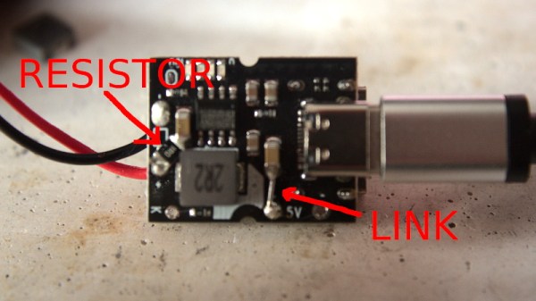
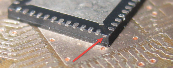
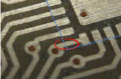
The PCB layout just happens to have a trace exiting right under this conductor. The two aren’t touching, but without solder mask, a bit of melted metal was able to mind the gap and connect the two conductors. [Eric] notes that although the non-pad isn’t documented, it’s easy to prove that it is connected to ground and was effectively pulling down the signal on that trace.

In a recent article on Hackaday I talked about “dangling pointers” and the challenge when interrupts expose the bug. [Erich’s] covered a ton of posts about embedded software. I was doing some poking around and was delighted to find that he covered the same concept and a solution for it using a program called cppcheck.