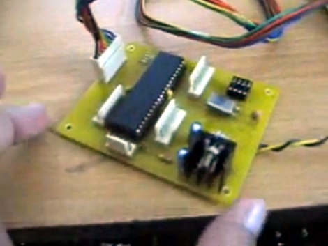
This programmable power supply is the perfect addition to your bench tools. [Debraj Deb], who previously built a whole house power monitor, designed this build around a PIC 18F4520 microcontroller. The desired voltage is set with an attached keypad, resulting in a digital output on the 8-bits of port D. The port connects to another protoboard with an R-2R digital-to-analog converter resulting in the target voltage. A set of transistors amplifies the current and a power transistor then takes care of the final output. After the break you’ll find two videos, the first walks us through the hardware and the second demonstrates the device in action, along with measurements of its performance. This certainly provides a lot more functionality than an ATX power-supply conversion.
Update: A big thanks to [Debraj] who sent us a code package as well as the schematic (PDF) used during testing. We’re having trouble getting the code package up for download right now. Check back later, hopefully we’ll have it up soon.
Part 1
[youtube=http://www.youtube.com/watch?v=d6XO1oouZm8]
Part 2
[youtube=http://www.youtube.com/watch?v=zUTZ4zQ2HoA]


Neat !
Thanks for sharing :)
Nice and simple. Might I recommend a buck-switcher version as well?
“003 . . . it is again ahhh close to about . . . ok it is not very close but it is significantly close to 300mV”
haha I laughed so hard at this part, this was a great idea with a great implementation, and I like that even without “perfect” results Debraj wasn’t afraid to let us see the multimeter. Props!
nice!
Any source and schematics?
never mind just saw the update
next step would be read the output voltage with the PIC ADC for a closed loop self regulation?
this is going to sound like a silly question, but why does every workbench need some crazy power supply. everything i do runs on 5vdc. so i use a 5v wall adapter and some voltage regulation and im ready to rock. what am i missing here?
walt:
If you only work with 5v, then you are missing the entire analog world.
@Walt
I agree with you mostly in practice, but if you are working at all in the analog domain, you are going to need a couple of different voltages, plus negative voltages. This sadly doesn’t cover the negative voltages, but it helps out with generating 15v, 12v, 5v, AND 3.3v, all commonly used voltages, in an easy to use and well designed package.
Aside from the need for voltages other than 5V, (which is for rather antiquated devices anyway; most fun things, like FPGAs, DSPs, etc. run on 3.3V, 1.8V, or even less), an active current limiter is an absolute must for a lab supply.
There are a few things seriously wrong with this design. For starters, it looks like he used standard 5% resistors for the R2R ladder, this is a FAIL in itself. An 8-bit R2R ladder has a resolution of 256 divisions, so using 5% tolerance resistors is not only terrible for accuracy, it also means the whole thing isn’t monotonous anymore.
There is no gain control around the opamp, which is another huge beginners mistake. The thing is probably oscillating like crazy, but the output capacitance is so big you can’t see it on the scope. This huge capacitance also makes it very slow, as you can see whenever he changes the output voltage.
The circuit diagram doesn’t show any kind of current measurement or control.
There doesn’t seem to be any kind of power supply decoupling whatsoever.
There are far better designs out there, with complete schematics, proper voltage and current regulation (down to 0V and 0A), complete with source code.
This guy has a lot to learn, but at least he’s trying.
@Martin Meier:
He’s already using an analog control loop. Using the PIC’s ADC as the only feedback source is much too slow for lots of real loads, and will have very poor load regulation.
It’d probably be worthwhile to have a slow control loop via the PIC’s ADC to fine tune the output voltage though, as it appears his accuracy is quite poor, probably due to the R2R DAC.
@Sparky:
Yes. I agree that with 5% resistors, the monotonicity is lost (or degraded). Especially at numbers like “0000 0111” to “0000 1000”. I plan to change the entire DAC setup to MCP4725. Its a 12-bit, 5V DAC from Microchip. Using this will give me 3 advantages — 1) the interface is I2C, which will let me use lesser pins, 2) I will have higher resolution (8bit vs. 12bit) and 3)No issues with 5% tolerance resistor :-) This demo is more for a proof of concept.
On compensation of feedback amplifier, yes, there are huge oscillations and I have to work out compensation — capacitors in -ve input to output, but did not had the capacitors around, so managed with a large capacitor on the output. Also, I am OK with slow response which I feel is better than overshoot from set voltage.
I have provision for current limit. Check the blue color shunt resistor (0.15ohms) that I have on my analog board. I am yet to amplify the current signal thro an op-amp and feed into the controller. That part will be covered in the 3rd part of my video.
Power supply decoupling, I have not shown on the circuit, but they are integral part of the hardware.
The programmable voltage is pretty cool, but you should really make it a switching supply. Then you can go for MOAR POWAH, like a 100 amp polyphase electrochemical beast, or a 385 Vdc supply with power factor correction, when you want to build a big honkin’ power amplifier (motor control? tesla coil? induction heater?).
@error404
thanks for the explaining.
I like the idea and all, but isnt a 40-pin PIC18 kind of overkill? Id like to see this done on a PIC12. That would be impressive.
Was the code every posted? I am interested to see how he setup the button input…