Here’s a nifty programmer for a cheap Bluetooth module. So just how cheap is this part? Does $6.60 sound like an extreme deal?
The information on this hack is spread throughout a series of posts. The link above goes to the completed programmer (kind of a look back on the hack). But you might start with this post about module firmware options. Just because you can get the part inexpensively doesn’t mean that it’s going to work as you expected. [Byron] sourced similar devices from different suppliers and found they were not running the same firmware; the footprints were the same but he features were not. With his help you can tailor the code to your needs and reflash the device.
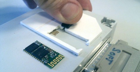
The programmer that he build has a nice slot for the module which interfaces with the programming lines using pogo pins (spring-loaded contacts). It connects to the CSR BC417 chip’s SPI pins in order to flash the firmware. If you’ve had any experience working with these cheap parts we’d love to hear your tale in the comment section.
[Thanks MS3FGX]


Very nice !
Here’s what I did with a similar cheap bluetooth module:
http://trandi.wordpress.com/2012/01/13/spoka-night-light-controlled-from-and-android-phone/
Make an Ikea night lamp remote controllable by an Android phone…
Dan
I’ve been working with one of these chips in my current project. I purchased the Deal Extreme version, but it took over a week to arrive and I was unable to solder wires directly onto the board so I’d recommend getting a breakout for it. A US based supplier (mdfly) exists and they sell both the chips, the breakouts, and the fully assembled unit. They also have all datasheets that I’ve needed to interface with the device.
http://www.mdfly.com/index.php?main_page=index&cPath=8_47
I had problems soldering to one of these units myself. Here‘s a thread on a very neat way to do it by wrapping uninsulated wire in a spiral around the board in the scalloped indentations, soldering them in place, then trimming the wires. I just wish I’d found the advice before I got my module!
Cool, I’ve been looking at these for home automation.
Ideally you could use the BT module’s CPU directly, it has enough IO pins for simple tasks. Unfortunately CSR don’t make their dev tools freely available.
@feedayeen: for soldering, you can wrap bare tinned wire around the notches in board to make a helix, solder in place, then trim the excess off to leaving pins.
Nice work getting the programmer working, just wondering if there are any different profiles available that give access to all of the pins? RTS/CTS and usb access would be incredibly useful.
Anyone know where we can get different firmwares for the boards (other than the ones on the blog)?
I guess you can build your own firmware if you have BlueLab, but it’s not free. If you google Bluelab 4.1, there are a few links to download it, though I can’t say if it’s legal or not.
But with Bluelab you can only write code for above the HCI layer, but if you wish to code for below HCI is there any sdk+module/hw available?
thanks,
justin
By the way, I made this adapter for that module http://www.alfersoft.com.ar/blog/2012/01/22/protoboard-adapter-for-cheap-bluetooth-module/
It worked for me, if you want to experiment on a protoboard.
Byrons Blog is excellent and i found it most helpful.
The only drawback with this cheap device is that it is only CLASS 2. Which is nominal distance of 10 m but in a house you will loose packages even if you’re not in the same room.
Does anyone has a source of cheap class 1 devices?
I also use this module with the standard firmware. It’s quite nice, but the configuration is a bit strange. You have to send AT commands within a define time frame. But you only have to do this once. After that the module looks to both you microcontroller and PC like a normal serial port.
The limitation is that you can’t make this module connect to other modules. It’s slave only.
One can also try to get the SDK “Bluelab 4.1” from CSR to write own firmware. These chips are quite powerful and have lots of built in features.
you describe the HC-06 limitation (livor firmware).
The goal of my blog is to upgrade these modules to enable master mode and other cool stuff !
i love these chips, flashed some bluegiga firmware (available on their site) to them, works like a charm. i would never dream of doing such a thing for commercial reasons, but for a weekend project it was interesting.
Inquiring minds want to know. What model/version of firmware would you suggest one start with?
For a friend of course.
Could this be used to create a wireless game controller? The AT command specs explain how to declare it as a gamepad, but does this mean the host computer will recognise and automatically configure it as one?
I’d love to use this in an NES controller.
it will be the subject of a future article.
I’ve found some SNES controller for few bucks on ebay…
DX also sells a version soldered on a board, with male headers.. Slightly more expensive, but works great.. (though it comes with the more limited firmware)
http://dx.com/jy-mcu-arduino-bluetooth-wireless-serial-port-module-104299
If CSR and Broadcom didn’t treat this stuff like some kind of federal secret, there would be so much cool stuff we could easily do with all these cheap Bluetooth devices.
I have also designed a minimal breakout board for this BT module.
http://entropia.kapsi.fi/mrie/btproto.jpg
I’d be interested in getting a firmware for these devices that can do audio over the PCM interface, for example. That’d be great!
Do you have any of these boards for sale? I could do with a couple for a project I’m working on.
Dave.
i just bought 3 please tell me these are these things good?
i have a breakout that fits its design collecting dust so the solder directly on the pins issue.
Yeah, they totally work at least for the basic serial mode.
Pair them to your bluetooth host (tried on Windows), and you get a virtual Comm port immediately.
I like the design of Byron’s programmer.
I also have designed a simple breakout board for breadboard prototyping. It is compact and allows easy access to the SPI programming pins.
http://elasticsheep.com/2011/09/bluetooth-module-breakout-boards-are-back-in-stock/
Still available for orders if someone is interested.
Hah…the breakout board costs more than the bluetooth module itself!
Yes, but the next ten thousand will be cheaper ;)
Byron’s blog is excellent. It helped me a great deal when I was trying to get my chips to work.
The only drawback with these cheap devices is that they’re class 2. That’s probably fine for most applications but in my circumstances I noticed that in fact walls absorbe quite a lot. So class 2 chips are in my opinion not suitable for home automation.
Does anyone has a good source for similar class 1 bluetooth devices?
Does the moderation work?
Sorry for my last post regarding moderation. I’ve tried to publish a comment and it always said: “awaiting moderation”. Initially I thought it is related to some keyword but just now I found out that apparently it is linked to the “name”+email address. So once you use a different pseudonym but the same email address your comment will be marked as “awaiting moderation”. Not quite sure how good that moderation technique is…
Anyway… enough of the rant… what I was initially going to say is the following:
Byron’s blog is excellent as it helped me a great deal to get started with the same module and test the alternative firmware.
However, there is one major drawback with these devices for my purposes as they are just CLASS 2. That’s probably fair enough for most users but the nominal distance of 10m will never be reached if there is a wall (or a floor) inbetween. so for most home automation applications Class 2 devices are not of a great use.
I’ve even used Class 1 devices but they tend to be far more expensive and the nominal distance of 100m will not be achieved in a house either. Unfortunately by law the class 1 devices use already the highest allowed transmission power.
The 100m distance will probably only be achieved if the receiver sensitivity is extremely high. E.g. you have to use only Class 1 devices (my tests were perfomed were one class 1 device communicates with a class 2 device).
Does anyone has a source for cheap BT class 1 devices?
Does anyone has a BT class 1 device with an extremely high input sensitivity?
Hey if you’re still on this blog, do you know where I can get a reprogramming device for a class 1 bluetooth chip? (which is what I believe you’re looking for)
Yeah these are great! I’m using one to configure my arduino in a project. Using the break out mentioned above. Also appears to have a voltage regulator as I run 5V no problem.
Depending on your PC/drivers you can set the duino to 57600 and then the bt module to 57600 and upload sketches. Saved me hours of mucking about with cables.
Also testing one of these units coupled with a MAX232 to provide a bt serial port to my ASUS transformer (using Blueterm). So far looks like I’ve got a dud, going to have to get a replacement – got it on ebay :(
I knew the firmware could be changed but not that it was so easy. Now I might do it too, thanks. Here is a picture on dx of my module soldered to be used on a breadboard: http://www.dealextreme.com/customerphotos/quarantined/201109/80711-74857578-9ef7-4b26-9064-1507dc9cb5eb.jpg
I tried posting this yesterday, but I must’ve done something wrong. The mention of spiral wrapping wrire as an adapter reminded me of a protyping writeup for a SMD to DIP (or other) adapter where I was surprised to find, I’d never posted the final installment. Since I’ve never seen the method posted on the web, and it works for almost any 2- or 4-sided chip/module, I’ve finished it now. http://www.exisle.net/mb/index.php?/topic/65765-a-cheap-and-easy-way-to-make-smd-to-dip-adapters/
Does anyone have any BlueLab code examples to control the digital IO lines?
For example, is it possible to control the IO lines for simple logic without requiring the use of an external MCU? Ie, could we create an RGB light controlled by bluetooth that didn’t require an additional MCU (maybe just a small number of support components). Can one design a custom firmware to respond to bluetooth commands (from say a program on an Android phone or similar), and use those commands to do PWM on the IO lines?
More useful information here:
http://myrobotlab.org/node/118
The big question is, has anyone the possibility to run own code without the need of bluelab/casira on that bc417.
Otherwise it’s nothing more than a reasonable processor doin’ almost nothing.
look at bluegiga stuff.
for sure you can !
the bluelab SDK provides you some example code !
@Reggie: Which bluegiga stuff, i can’t find anything where you don’t need login credentials.
@Byron: Problem is, i’d need bluelab SDK for that which is a) quite expensive or b) would be not legal to use if i get it from somewhere else
it seems it is not very legal… but i don’t pretend to make some money with this.
I FINALLY received my module from DealXtreme yesterday. Only a month later… :-P
I signed up for CSR’s developer program, but they won’t give me access to anything helpful yet. Any suggestions on the software?
Nevermind, I think I found what I was looking for here: https://www.csrsupport.com/PCSW I guess we’ll see.
i like this
Does anyone if there is a bluetooth module/chip(like open embedded h/w etc) which will let me code my bluetooth code for below hci layers(lmp, baseband)?
CSR doesn’t like to give even basic datasheets if you don’t promise to buy a million chips.
The CPU can be used for a lot of things. Bluegiga runs a large number of profiles, their own stack and custom gpio functions as special profiles on it but trying to get your own code to run on the modules might be hard.
As for range, one of the longest range BT modules available is Bluegiga WT41, with an external omnidirectional antenna the range can be 1..2km and even with the chip antenna around 800m in open country. The 100mW limit and the modulation used on BT will likely limit the maximum possible range to a few km but anything less than 1km are just compromises in cost, antenna size etc. No class 1 module will output anything near the 100mW limit, the practical upper limit is 60mW and most modules will really only give something like 20mW, cheap chip/pcb antennas will reduce the range a lot and bad application board layout for the module antenna end will ruin the antenna performance.
If you can manage to get a copy of BlueLab, you can write ANYTHING for the chip while programming the device via arduino-spi pins: (Hebrew post) http://www.makers.co.il/mfs/showthread.php?91-%E4%EE%F8%FA-HC-03-Bluetooth-Module-%EE%E1%E5%F1%F1-CSR-%EC-HID-Device
HLL, Thanks for the pointer. After Google translation, it seems to me that HC-0x BT devices can be programmed as a stand-alone MCU/BT combo through SPI interface using an arduino? This sounds very intriguing to me. Do you know of any tutorials that would lead me through the details?
100mW will go a long long ways with the right antenna. It just gets very directional.
This is one of the more popular how-to guides for using the HC-05 bluetooth with the Arduino.
http://www.instructables.com/id/Cheap-2-Way-Bluetooth-Connection-Between-Arduino-a/
Buy Bluetooth module, Bluetooth arduino, Bluetooth usb adapter, Bluetooth bee from here: http://www.elecfreaks.com/store/products_new.html