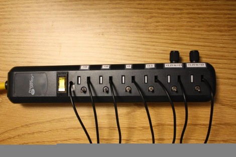
Back in his college days [Print_Screen] grew tired of always building a power supply on his breadboard. To make prototyping quicker he came up with the bench supply that is build into a power strip. This one is using linear regulators for power, and create much less noise on the lines than a supply made from a switch-mode PSU.
First thing’s first, he needed to step down from mains voltage and rectify the AC into DC. He gutted the smallest adapter he could find and managed to fit it into the gutted power strip. It puts out 15V which will work perfectly for the regulators he’s chosen. Each one gets its own slot where an outlet is on the case. The ground hole has been plugged by a toggle switch which routes power to the free-formed regulator/capacitors/heat sink modules. There is a slot for 15V (coming directly off of the converter), 10V, 5V, 3.3V, and two variable regulators which are controlled by the knobs above the outlet. We’ve never seen anything like this and find it most excellent!
[Thanks OverFlow636 via Reddit]


I don’t know about you, but seeing wires stuck into an 110V outlet like that makes me feel uncomfortable lol
“the smallest adapter he could find” it would be wise to include a current regulator of some sorts or a fuse, a lot of those small power supplies you can find have really low current output abilities, and some will mention only the peak output, and continuous use could be afire hazard. Not trying to be a safety Nazi, just a fair warning.
Yeah, that was my first thought too. Might be good for a few hundred milliamps. Then I looked at his photos and it looks like he used a 15v switchmode supply, so it may be good for an amp. Of course this counters what Mike said in the posting, so I’m not sure.
Why using Lm2937 instead of LM7805, LM7812… etc?
Sorry if this is a stupid question, im newbie
The regulators used are limited to 500mA. Putting male cables on a power source is never a good idea. Always use female connectors when something is sourcing current. Always.
Why’s that?
Think of your wall outlets. It would be scary if instead of holes all the outlets were little metal prongs sticking out.
haha… of course
That is pretty clever
By me, this is not a good idea. No binding posts !!!
That is the most dangerous looking power supply I have ever seen
looking closer at the power supply used it really is the most dangerous bench supply I have seen, that switching adapter is not isolated.
Aren’t most of these little two prong switchers isolated? Looks like a small transformer in there.
Well that photo sure made me do a double-take, until I read what was going on.
Shame on Mr. Szczys for adding false editorial details: “This one is using linear regulators for power, and create much less noise on the lines than a supply made from a switch-mode PSU.”
Really? I don’t see anywhere in the link where the author measured noise levels, so you’re just assuming.
In fact, there’s a switching PSU as the main 15V supply.
Yes, it’s stepped down to the other voltages via linear regulators. But they’re notoriously bad at passing high frequency noise without any significant attenuation. Which is exactly the kind of noise that comes from a switching PSU. Especially a tiny, el-cheapo supply like the one like used here.
So for all we know, the noise could be worse than the average ATX supply.
Really, binding posts are not expensive enough to make this look like a good idea.
Nicely done! I would have put the switches where the black wires come out, and binding posts in the ground holes. Less messy and safer if accidentally left on.