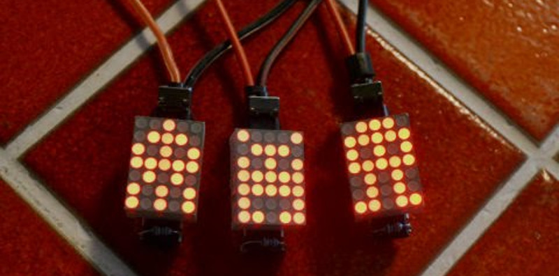
If you want to mess around with some microcontrollers but don’t really have a purpose in mind this project is perfect for you. It’s cheap, easy to assemble, and there’s blinking LEDs! [TigerUp] shows us how he put together some LED matrix pendants using just five components.
He calls the project Tiny Matrix, which is fitting as the pendant outline is barely 0.5″ by 0.7″. On the back an ATtiny2313 chip has been soldered directly to the legs of the LED display. They just happen to line up with I/O pins on the chip which makes for super simple soldering. Power comes from a coin-cell which is connected to the pendant by a red and black wire which make up the necklace for the device. The last two components not yet mentioned are a momentary push switch for changing modes, and a pull-up resistor on the reset pin. The bill of materials rings in at $4 and his firmware offers up nine different modes as you can see in the clip after the break.
[TigerUp] was inspired by this 8×8 matrix project.


I love this… but must wonder how annoying those wires are, being so thick.
Related Idea:
Chest pendant tetris, controlled by squeezing boobs.
Cheating in Chest Tetris
I couldn’t find any info on the Lite-on led matrix, and couldn’t find evidence of PWM in the source code… so what’s keeping the LED cells from over-currenting? The coin cell internal resistance?
Oh, nvm… Duhhhhh, most likely the current source limit on the output pins…
It’s early.
Hmm nope. 40mA out max on those pins. I guess the chip or the leds will burn out eventually.
Having a serious internal struggle today. The scanning nature of driving the individual rows (or columns, or whatever) is like a PWM. So the matrices might last quite a while before burning out.
Arguments with myself.
Well at least you can see my thought process =)
More coffee?
I think you got it right the first time. The coin-cell resistance is pretty high. That’s why those little coin-cell based flashlights don’t need a series current limiting resistor. A scope attached to the VCC pin would probably show a large variation in supply voltage. I guess it always remains above the brown-out voltage of the uC.
Connect this to a low-impedance power supply and then I think the current limiting will come from the pin drivers. And they will eventually be damaged. The peak current for this multiplexing system is probably less than the max the LED spec indicates (typ 100 mA for low duty cycles).
So he is using the internal resistance of the coin cell battery to limit the current – that is an excellant hack!
Just be sure to not switch to a couple AA batteries without adding a resistor
A coin cell can’t put out more than a couple of milliamps. Between that and the multiplexing the LED should be quite safe.
The ATTiny can handle driving the LED’s directly?
Or does the software turn the LED’s off quickly before they can draw too much current and blow the micro?
he’s using attiny4313???
Show me the code ported to MSP430G2553 and I am sold. I will make 100 kits, sell them at cost and ship free to those interested.
The code is written in C! Porting should be more-or-less trivial. The question is does the MSP430 have a pinout where you can squeeze the LED matrix on top of it.
It may seem immature, but DAMMIT I love blinking lights. It’s instinctual I think.
http://www.xobmomacbond.info/pics/msp430_tssop_DIP.jpg
Totally want to take you up on this offer if it happens to work out. :)
I love this. Put me done for 4 when you get going!
PS don’t ever have me take a picture of a leaked product…
Do people realize that the attiny has an internal pull-up resistor on it’s reset pin?
For large project adding an external one won’t hurt, but with such a low component count it makes a difference.
I did not know that! Thanks for the tip.
T
If the the TigerUp guy ends up in here, i’d love to see him discuss the idea behind the “Fire” animation generation. It’s not immediately obvious from the comments what inspired the code… and its super elegant.
Hi Sam,
The Rain and Fire modes both use the modulus math operator to divide the “frame” counter into regular cycles. For example take frame (which gets incremented by hardware interrupt) and modulus it by 10 (frame%10). You’ll get the sequence 0-9 repeated forever. Now plot points based on these, and it will give regular periodic motion. I used relatively prime numbers so the repeats aren’t obvious.
T
How about making these things as earrings (LED front, battery behind.)
May be a bit too heavy & thick… For that i’d look into a custom matrix of SMDs. Otherwise the other dimensions are great!
I’m going to try it with an MSP430…
drop me a line about the MSP430, primary_admin at xobmomacbond dot com
I meant info
what do you do/use to program the tiny?
The internet is your friend
http://hackaday.com/category/attiny-hacks/
https://www.google.com/search?q=programming+a+ATtiny4313&ie=utf-8&oe=utf-8&aq=t&rls=org.mozilla:en-US:official&client=firefox-a
Does anybody know where to find the displays in Europe? (Jameco has $30 minimum order + shipping)
Greetings from Idaho! I’m bored at work so I decided to check out your blog on my iphone during lunch break. I really like the knowledge you provide here and can’t wait to
take a look when I get home. I’m shocked at how quick your blog loaded on my phone .. I’m not even using WIFI, just 3G
.. Anyhow, amazing site!
How would one go about changing the animations/static images? I can see that they are all hex code, but how would you go about even learning how to fiddle with them?
So looking at the project information, I can understand the basics and see what I’m looking at, but I’m wondering how you would know how to change the pictures to something different than what is given… Any tips or links to information that would be helpful?
So without getting into the exact specifics of the code, I can assume that since there are 5 hex codes associated with each 5×7 “image” that each hex code is associated with a column. From the images I deduce that the least-significant bit starts at the “top” of the LCD (the side with the necklace loop).
Let’s take the heart example. The first column from the bottom is: off, off, off, on, on, off, off. Or in binary from MSB to LSB: 0001100. Or in hex: 0x0C. If you look in the code, the first hex byte reads: 0x0C.
Continue the pattern for the 2nd thru 5th lines and you’ve got a complete image.
That… makes perfect sense :D I got as far as getting the 5 values = 5 columns and seeing that they were hex codes, and then my brain died.
That’s what I get for trying to look at code at 3AM