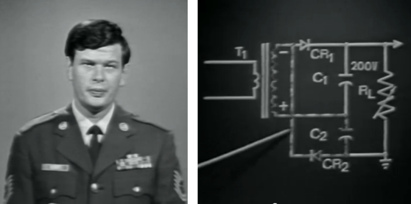
This very stern looking gentleman is about to explain how voltage doubles work in a plodding, yet satisfyingly thorough manner.
We’re not certain when this US Air Training Command video was produced. Obviously it was used to train servicemen who were responsible for keeping electronics running during war time. We’re glad for that, as they really found just the right balance to present a concept that required some knowledge, but is approachable for even the most basic of new electronics hackers.
The demonstration board shown on the right is the voltage circuit highlighted in the lesson. Here the pointing stick is being used to trace out the circuit function during one phase of the input transformer. The capacitor/diode pairs rectify the voltage, with the capacitors discharging in parallel series to double the output voltage. But how does the variable load (RL) affect the output? This is demonstrated under several different conditions using an oscilloscope to illustrate the change.
The discussion of how the diodes work reminded us of a modern tutorial we just ran across this weekend. It’s a bit bizarre, but explains the PN junction in a different way than we’re accustomed to. In this case you will already need to be familiar with how semiconductors work to understand the presentation.
Both clips can be found below the jump.
[Thanks Katja] for the voltage double tip
PN Junction video found [via Reddit]


hey, i just watched the “modern tutorial” video and that’s exactly how i was taught pn junctions(minus a bucket load of math), so im just curious what is it you are accustomed to?
yeah, I got bored quickly and started skipping through it (she talks in damn near monotone), everything I saw was pretty standard. significantly more in depth than a lot of explanations, sure, but definitely nothing crazy.
There’s a 2003 Microchip PDF which has a bunch of microcontroller tips’n’tricks, number 10 shows how to get a higher voltage by using a PWM pin with 2 diodes and 2 capacitors:
http://ww1.microchip.com/downloads/en/devicedoc/40040b.pdf
I discovered this being used on the DIY scientific wristwatch http://www.calcwatch.com (for some reason Google reports it as being an attack site, yet the only external content appears to be Google Adsense…) where he used the technique to power a 5v LCD display from a 3v coincell.
I tried it myself with a Picaxe chip, PWM output at 10khz with 50% duty cycle, 0.6v drop down diodes with 0.1uf & 10uf capacitors and tested different input voltages to the microcontroller to see what I got on the output (with no load):
3.3v outputs 6v
3v outputs 5.4v
2.5v outputs 4.44v
2v outputs 3.47v
he nice, pretty good to result and indeed handy for LCD stuff
fyi: http://www.calcwatch.com/ is an old design from Dave Jones ( eevblog ).
Put 10 voltage doublers in series. You’ve increased your voltage 1,024-fold! Power your house with a 9V battery! [/trollphysics]
How is it “trollphysics”? You just described something called a Cockcroft-Walton Generator, or a Marx Generator.
You got trolled. Cockcroft-Walton Generator gives you N times input voltage for
N stages, not 2^N. So output = 10X not 2^10 = 1024.
Well, this is assuming that the doubler modules all have the same capacitors, diodes, timing, etc. In theory, you can in fact stage them to get something like 10KV from a 9V battery. And I don’t see how it’s trolling to realize that you could run your house for a very small fraction of a second or only a 1w lightbulb on that setup? :P
Normally, these are called divider-multiplier circuits and not just doublers. For example 3 capacitors in series. Switching power supplies can use this idea trivially in a capacitive mode, although scaling up the wattage is not so trivial. Might want to Google “Buck converter”.
Sorry to say, the cap’s are discharged in series, a vintage circuit having many manifestations.
D’oh…. fixed.
Noob question here… wouldn’t it be simpler to change the ratio of the transformer?
Short answer, no.
What comes out of the transformer is AC. If you want DC you’d still need to put 4 diodes to rectify transformer’s output. So just keep those 2 caps and 2 diodes and suddenly you don’t have to find a transformer with half the ratio :)
well, yes but won’t this generate a lot more noise than a traditional rectifier + capacitor? Dave from eevblog shown a similar circuit some time ago but he if i remember correctly the example was generating the ac from toggling a microcontroler pin then boost it to power an lcd, in this case we already have ac, we already have a transformer, the only reason i can think to go at it this way is if you can’t change the output of transformer nor get another tap. Am i missing something is this is the idea of the movie?
answered my own question… need more coffee, still the circuit shows a neat trick
Sometime, it makes sense (and cents) not to pay for a transformer or one
with multiple windings.
Back in the older days when your PC used to a 110V/220V switch on the
PSU. They actually use full wave rectification for 220V and a voltage
doubler for the 110V. In this case the voltage doubler consists of the 2
dioded from the bridge rectifier and the switch simply connects the
neutral wire to the mid point of the caps.
BTW The rectified DC is used to run the high frequency DC/DC converter
inside the PSU.
So would you pay for a huge transformer or redesign the DC/DC stage just
for the 110V market?
In terms of noise, the ripple is like that of a half wave rectification. Nothing
that can’t be filtered out or handled.
I am quite impressed the video effects they put in to the B/W video. How did they overlay the video of oscilloscope to the main video in the absence of modern computer?
you projected both to the same screen and film it.
You can also use a trick that light painters are familiar with. Record one scene and then wind back the film and record again with the second scene. It’s a cheap additive blending trick that works wonders. Some film makers were even clever enough to use tinted lenses to adjust the degree of blending.
Ugh, they’re using electron current, instead of conventional current. Nobody teaches it that way anymore!
Haha they’re doing it a perfectly correct way IMO. For the longest time I didn’t understand this concept, and I think everyone who works in electronics should make an effort to.
For those that don’t know, here’s my understanding:
It makes sense to think of current as the flow of physical electrons (they actually go from – towards + terminals on a battery)…this is your electron current. There is a surplus of electrons on the (-) terminal, so they want to flow to the positive terminal to balance out.
The modern way is to think of current as a flow from + to – terminals. This is also correct, but in a different way. I view this method as a movement of positive charge +. As electrons move to the + terminal, the overall flow of positive charge is actually towards the negative terminal….the opposite of the former idea of current.
http://xkcd.com/567/
Is it really the “modern” way? I always thought it was a misconception that some how become mainstream. After all, electrons are real thing and positive charge is not. It is kind of like saying “vacuum” is the force sucking dirt into vacuum cleaners.
Current is the movement of charge. Positive charge is moving in a direction opposite to that of the negative charge. Using conventional current makes writing the circuit equations simpler to me. I showed it to a friend of mine who teaches high school students, and it was easier for them than using the method their Physics book taught.
I thought the same. A misconception that they stuck with because so many of the existing books used it. This is back in 1798 or something.
It is about time it changed. It’s impressive that doing it the wrong way round has worked so well so far, relativity for ya.
All they need to do, is decide electrons have a positive charge instead of a negative one. It’s an entirely arbitrary decision, like which way up to make a globe. Electricity makes more sense if it flows from + to -, so just fix the mental model to match the physical one.
AFAIK current is still the movement of electrons in a conductor, yea I know electron has been replaced by charge. IMO the time they realized got it wrong they should have started using what the new science was showing them,that’s the way science is supposed to work we are told. Yes additional science had to be taught when semiconductor active devices hit the scene, but the modern way doesn’t explain the operation of vacuum tube. Vacuum tube operate a lot each day in the homes of those who can afford a microwave oven. [shrug]
These circuits were often used with switches on motor drives for a company I worked for to change the output bus level.
I remember this type of video from when I was in the USAF (mine were medical). The code on the film says it was made in 1970.
Bizarre? My modern video on PN junctions? Hahaha xD
Thanks for using it in your webpage! I love feedback from users! :-D I take seriously your comments, they help me to improve for my next ones. Thanks! Have you checked the one on MOSFETs? http://www.youtube.com/watch?v=QO5FgM7MLGg
Best Regards
Francisco