![]()
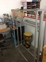
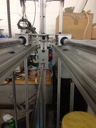
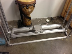
The presence of a camera in this image may be a bit confusing since we’re calling it a scanner. What’s actually going on is that macro-images this piece of art are being captured automatically. The multiple shots will later be assembled into one fascinatingly high-resolution image. The CNC scanner rig is [Charlie Romer’s] summer project.
Unfortunately [Charlie] hasn’t yet collected all the information on the project into one place. After the break you’ll find more images, as well as a few demo videos. The best place to start is probably his proof-of-concept from this Spring. He shows a single-axis CNC mount for the camera. It takes an entire row of images. The assembled photo from that test is shown below. We believe the faint yellow dots in the macro part of the example are fingerprints purposefully left by the printer called printer stenography to help prevent forgery.
The larger rig uses movement on two axes. The idea is that the artwork will be perfectly positioned so that manual focus set at one point will work along all points in the capture routine. He’s using a lamp for a light source but we’re sure he will upgrade so something like a ring light as the project continues.
In Production:
Proof of concept:
Gantry demo:
Full rig first run:


He should use cross-polarization.
… stenography”, maybe respelling the word helps…
lol, I don’t think printers do shorthand. A plotter maybe?
I don’t think dinosaurs did CAD. A trilobyte maybe?
I like it, I got the same idea about year ago when I saw great graffiti art. Never got any further from the idea though.
I would be cool if he open sourced the camera control electronics and software.
That is going to cost a lot of clicks, camera will wear out fast when doing this daily
Nah! Must be plenty of clicks in a camera. Since the optics are set on “macro”, I’d guess the little focus motors don’t get much exercise. They’re about the only moving parts, what else can wear out?
The shutter? I think they tend to hover around 100k exposures, but don’t quote me on that.
The D800 shutter is rated at 200k cycles.
And one can use live view.
There is no need to torture physical shutter really.
Even if Nikon recommends changing the shutter after some 200k I have seen Nikon cameras where the shutter hummed along nicely for another 200-300k, thing is that it doesn’t magically break down at 200k, it is just that at around 200k Nikon can not guarantee that the timing is accurate anymore.
Shutter drift becomes an issue after 200k with the higher speeds unless you start to use a flash system at which point 500th of a second is all you really need since the flash does the exposure timing for you.
(I used to work as a customer, retail and NPS technical advisor at Nikon Sweden a few years back)
neat idea.
Maybe have it computer controlled, where it can check the images for the edges, and automatically figure out the dimensions of the scanned object.
Nice work! I wonder how this compares to the systems currently being used by libraries and museums for archival purposes.
From what I have read they use cooled monochrome cameras with filter wheels to get their images. Less noise and no bayer filter issues like moire.
They also use known spectral emission lamps with very narrow bands in some cases.
The science of forensic photography is slowly but surely making it’s way into the Museum and art gallery world. Not without a certain amount of kicking and screaming as the art world is quite conservative.
(used to work at an art gallery before my time at Nikon and after I did an internship at the Museum of Sketches)
I have the same lens he is using, very nice, very expensive. Like $1800 new.
Some stuff I shot with mine:
http://www.flickr.com/photos/67292116@N00/sets/72157627041373036/
And your lens is even in focus!
You should see how many photos were rejected just to get those few. The depth of field at minimum focus and wide open is incredibly short, Something like .010″ or less. Hand holding the shots is rather difficult. The photos in this set were also taken with the lens using a high powered UV source and fluorescent dyes.
http://www.flickr.com/photos/67292116@N00/sets/72157629551557170/
Wow, ever try image stacking with that lens? Nice photos
What is the effective resolution, as measured with a test target?
I haven’t yet tested it with a real test card, but depending on the lens, camera, distance from the piece, etc. we have gotten anywhere from .5-11gpx in the final output. The piece shown in the last video was 1.4gpx. We are still in the early testing stages and still trying to nail down a solid workflow so I hope to get that up another couple gpx in the coming months. The real issue now is the closer you are, the more vibration is a factor in each of the images. I hope to add more vibration dampening and re-build the camera mount to reduce that.
You might try moving the picture instead of the camera. With that heavy of a lens and camera it is going to take some time to settle with that mount on the lens.
Hey, its Charlie here. Right now it has been setup similar to a Gigapan where you set the top-left and bottom-right of the image to be photographed, the size of the camera frame, and then the arduino calculates how many frames it will take to shoot. Since we are often shoot 360 panoramas, we are used to shooting hundreds of photos at a time so the camera shutter click count is not a big concern. I also wanted to give a shoutout to Calvin Domenico (http://www.dgftech.com/) who was my mentor during the build process. He helped me refine my concept.
I swear I just read this feature last month…
Hallo
I work on the same idea of scanning art-work but I use a different approach with an industrial robot.
More informations you will find at:
http://www.roboticphoto.com and the http://www.themachineview.com
have fun.
For years I have had an idea like this, and I am very happy to see such a project of similarity pop-up. I don’t actually have a project, only the ideas and the text (but they are dead like any other dreamer’s ideas). Here’s something I wrote last year that has some interesting ideas to contribute on this topic…
Source: http://www.joyunbound.com/www.joyunbound.com/2012/04/idea-dslr-scanning-grid-crane/index.html
For years I have had this particular idea that I wish someone would design, manufacture, and start selling. Here is the idea I have:
http://www.hlrse.net/Qwerty/DSLRcamera_scanning_table.png
With better design, a cube frame could even be constructed allowing the photographer to produce a matrix of photos for every axis (top, side, front). With this matrix of insanely high quality and high resolution photos, the photographer could use a program or script to do render or generate several things:
* 3D textured model or environment
* Parallax map
* Natural bump map (artificially possible via software like Adobe Photoshop)
* 2D texture
* Scanned image (as though having used a flatbed scanner)
This is different in that the idea is to construct an image that eliminates as much 3D perspective as possible
* Panorama (different styles; to better understand the descriptions, imagine a sphere with rectangular prisms extruding from it and the center of the matrix of photos focused smack dab straight on top of one of these extrusions)
Center appears 2D and flat, but as you move towards the edges the object reveals more of its 3D characteristics [i]leaning outward away from the center[/i]; like your typical panorama (convex fisheye)
Center appears 2D and flat, but as you move towards the edges the object reveals more of its 3D characteristics [i]leaning inward toward the center[/i]; like concave fisheye
Edges of object appear 2D and flat, but as you move toward the center the object reveals more of its 3D characteristics by showing all sides; inverse of concave fisheye
Center appears 3D showing all sides, outside edges of object appears 3D leaning outward away from the center, in between the center and outside is a 2D doughnut ring
Custom
I had forgotten to note that the tubes would also be hollow (more common sense), not solid, and that they should come in 2-3′ segments or something. My Canon t3i take 18 megapixel images (roughly 5200×2500 photos); that would be outrageously insane and high-end for application as a scanning device provided a tool like this idea. Some objects you could scan (let your imagination take it from there):
Motherboard
Apple
Teapot
Laptop
Firearms
Model or toy vehicles (cars, airplanes)
Dead insects, bugs, or animals
Rocks
Magnetic ferrofluid (I wonder if one could somehow record a 3D animation)
Moving liquids or objects (even better if somehow you could record it with multiple cameras simultaneously, whether taking continuous/burst photos or video)
Any questions and I will try to explain what I mean by particular elements of the concept draft.
The photographer would be responsible for their own lighting. However, that isn’t to say the design cannot take into any possible ways to assist the photographer. If you wanted to attain an image that was equivelant to that of a flatbed scanner, you would want the lights to move with the camera lens so that in the end you could have an image of an object (such as a motherboard) that appears as evenly lit as possible, has balanced lighting, and has a 2D-flat look to it.
How I came up with this idea was back several years ago when I wanted to scan a motherboard. Through this experience, I found that flatbed scanners are horrible devices for scanning anything other than flat sheets of material (such as paper). I found that the cameras that are built into pretty much all flatbed scanners are critically inferior to that of DSLRs. You have to flip the motherboard/circuit-board you want to scan upside-down, but then you wind up having a slanted object due to the uneven geometry (various sized capacitors and components randomly across the top-side of the board). Then, even when you do scan, you will find that the depth perception of flatbed scanners are so incredibly horrible that your resulting image is virtually unusable (except for the one or two capacitors that did lay flat on the glass). Try it, and you will know what I mean. The only solution: DSLRs.
You could set your camera to F22 and fine-tune your exposure. In the end, you could have a flat 2D, flatbed-style scan of your circuit board of a quality and resolution that competes with scanners that would otherwise cost you tens of hundreds of thousands of dollars (if you were seeking to attain the same kind of DPI, resolution, and how big of an area you could possibly scan – many scanners have only big enough glass beds for giant-sized paper, because they’re meant to scan documents, not circuit boards and objects with 3D extrusions and geometry). Or, you could even set it to F4 and focus on a particular layer.
If you had a very large glass table, you could take photos from above. With a basket of slightly varied design, you could have the camera sit above the crane-rails pointing upward, so that maybe you could assemble this device beneath your large glass table to take photos of an object from beneath.
Lots of potential, endless possibilities.