[Mark] was looking for a cheap disco laser projector for parties, and he found one. Unfortunately for him, the advertised features were a bit lacking. The “sound activation mode” was merely an on off circuit, as opposed to it actually being controlled by the music — he set out to fix this.
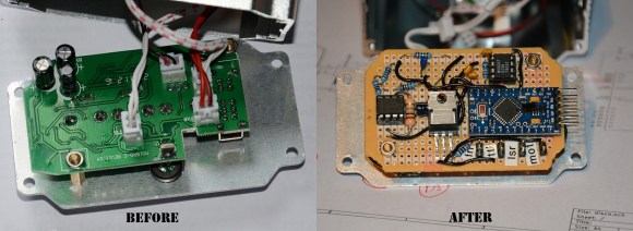
Taking the unit apart revealed a very convenient design for hacking. All of the components were connected to the main PCB by connectors, meaning the laser driver board was completely separate! He replaced the PCB completely using a prototyping board, an Arduino pro mini, a microphone with a simple preamp, a rotary encoder, and a MSGEQ7 chip to analyse the levels. Oh, and a MOSFET to control the motor via PWM output. It even ended up being close to the same size as the original!
If you happen to have one of these projectors and want to fix it too, he’s posted the source code and circuit diagram on github.
After the break, check out the before and after video. It’s still a cheap disco laser projector, but at least it works as advertised now!
[Thanks Mark!]


I thought the project was pretty interesting while reading it. But seeing the performance difference in the video really shocked me. Why in the world would they ship these things WITHOUT this kind of precision built-in? The patterns are so much more awesome when they are glued to the beat!
Because they expect people who use them to normally be drunk.
It could be taken farther. With a seven-band spectrum analyzer, part of the hardware is already in place to use some bands to intensity modulate the red/green lasers, like the classic “color organ”.
But I think the comments nailed why the manufacturer didn’t bother with any capability past what’s needed to claim “sound activated” on the box.
Some people who use them are drunk or otherwise intoxicated, and easily entertained by anything. Others quickly find the pattern repetitive, despite any small variations that could be added. So would the expense of better sound detection improve profits for the manufacturer in the end? That’s what it all comes down to, and I think it’s iffy.
Of course, [Mark] is not a typical customer, and probably derived as much entertainment from hacking it as watching it. ;)
oh fuck these party lights are SO GODDAMN ANNOYING! they’re overused due to their cost and the repetitive patten is just irritating rather than interesting – especially in confined areas….
I have always wondered if there could be a cool effect from the combination of the ‘spirograph’ laser effect (also a cheap party laser) and this diffraction effect….maybe i should get on that… /o_O/
Like a laser projected version of the Electric Sheep screensaver.
I found the effect to be lacking — it lagged the music far too much. It could be remedied by taking the audio and sending it through a delay line in length equal to the lag of the signal processing/motor control.
My understanding is that the disco lights listen to the audio using an on-board microphone. Unless I’m completely misunderstanding you, delaying the audio feed wouldn’t help with the lag since the device still has to “hear” it.
I thought that he gutted everything and replaced the controller — eg, it samples the sound, does a frequency analysis, and drives the motors in proportion to the bass component. If so, it should be possible to take the audio signal and feed it directly to the controller which operates exactly like it is, and externally, a delay line is used to postpone sending the audio to the amp which is driving the speaker system.
If his controller has a microphone input, then it shouldn’t be much work to rip out the microphone and feed the voltage (scaled appropriately) to the circuit from the audio source.
OK, I looked at his schematic, and you are right — he uses a mic to sense the audio. So rip out the mike and feed the audio source from before the delay line.
The MSGEQ7 is a spectral peak detector. It has a decay period, which is programmable in a simple fashion; in that it reduces the value 10% every time the chip is read (IIRC).
Perhaps a combination of reading the chip more frequently to increase the decay (I don’t know how often [Mark] does it), and partially compensating for motor inertia in the MCU, might produce closer tracking without a delay line.
The hacked version was definitely better, but after just 20 seconds of watching the “new” pattern, I was bor….
Oh look, something shiny.
I could also rotate to both sides instead of one..
pretty sweet!
Get a couple of linear polarized filters, mount them on a couple of motors whose speed and direction are controlled by adjustable picks from audio frequencies. Combine with the usual 2-axis “spirograph” audio driven laser deflection system, plus a second one of those setups for a second, different color, laser.
Have the polarized filters overlap as they rotate and fire the laser(s) through the overlapping filters.
Note that circularly polarized filters from sources such as RealD 3D theater glasses don’t do a thing (or not much) to lasers. Even layering a right circular polarized filter in front of a left circular polarized filter from those barely dims the laser. If they were perfect filters, the first would completely right polarize the laser beam and none would go through the left filter.
High quality linear polarizing filters (usually made of glass) will completely block light when overlapped at right angles.
One trick to make your own polarizing filters is to lay out strips of 1/2″ wide electrical tape, 1/2″ apart, on a large, white surface. Aim a film camera at the pattern from far enough away while still having the pattern fill the frame, take a picture, develop the film and the negative makes a good enough polarizer for cheap laser tricks.
That trick, amongst other DIY laser show apparatus, was in the October, 1980 issue of Scientific American. No laser? No problem! The same issue had a DIY project to build a mercury vapor ion laser.
that is sheer genius.
I happen to have a few sheets of linear polarizing filters. Got a link to what the effect looks like?
Did your disco light come with an IR remote? Mine did not. If yours did, I would appreciate any data that you can give me as to what IR remote format it uses (modulation frequency, encoding, number of characters, etc.). Thanks!
Can somebody PLEASE tell me where I can find replacement discs that rotate Lazer patterns. Google DOES NOT want me to fix this