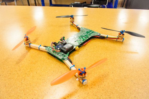
[Eric] has figured out a great way to build quadcopters out of recycled computer motherboards. Multicopters come in all shapes and sizes these days. As we mentioned in the last issue of Droning On, they can be bought or built-in a multitude of materials as well. Drones have been built using materials as varied as wood, PVC pipe, carbon fiber, and aluminum.
One of the more common commercial materials is G10 fiberglass sheet. It’s stiff, strong, and relatively light. Printed circuit boards are generally made of FR-4 fiberglass, G10’s flame resistant cousin. It’s no wonder [Eric] had quadcopters in his eyes when he saw a pile of motherboards being thrown out at his university.
[Eric] used a heat gun and a lot of patience to get all the components off the motherboard. With a bit of care, most of the components can be saved for future hardware hacks. This is one step that’s best performed outside. Hot melting plastics, metals, and resin fumes aren’t the greatest things to inhale.
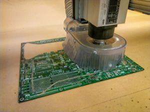
 Clean PCBs in hand, [Eric] headed to his local TechShop. He drew his dead cat style frame in SolidWorks and cut it out on a ShopBot. While a high-end CNC cutter is nice, it’s not absolutely necessary. The fiberglass sheets could be cut with a rotary tool or a jigsaw. No matter how you cut it, be sure to wear a mask rated for fiberglass resins and some protective clothing. Fiberglass plate is nasty stuff to cut.
Once the upper and lower frame plates were cut, [Eric] completed his quad frame with some square wooden stock for arms. The final quad is a great flier, and spare parts are easy to source. Nice work on the recycling, [Eric]!


While it’s nice to see the recycling in action, the frame of a multi-rotor copter is among the least expensive of all the components that go into one…
Cutting or drilling holes in components is an old hot rodders trick to reduce weight. Most likely that could be used to trim the weigt of if need whe using old circuit boards as a structural component, if need be.
Some nimble moves there. Cool use of scrap with easy user repair.
I also made my first tricopter chassis out of scrap PCBs. Then some bad code (I wrote my own flight control firmware) caused everything to suddenly throttle up, and though I had my hand on the chassis, it snapped into five pieces. I bought myself some 1/4″ plywood afterwards.
FR4 (the material most PCBs are made of) is pretty heavy. I wouldn’t have thought that was a good material for QC frames.
FR4 is an excellent material for multi-rotor frames. Carbon fiber is even better, but if you don’t have the money for carbon, some nice thin FR4 will do the trick, especially in a stacked frame design, which is pretty common with multi-rotors.
Then you would be very surprised to see many high quality quadrocopters using exactly that material. It’s usefulness is questionable when recycling. Most quadrocopters that use PCBs for the primary frame do it to route power. Some like the TBS Discovery will route both power and signals into the frame. http://team-blacksheep.com/products/product:98
Aluminium gives a stronger frame for the same weight as fiberglass. You need to use carbon fibre if you want to improve on that.
Aluminium bends and doesn’t ‘spring back’ like fiberglass or carbon will and in an impact hard enough, carbon or FR4 will break whereas aluminium will transfer the force of the impact into more sensitive components (flight controllers, esc, motors, etc). Aluminium is a great material for ensuring maximum carnage in a multicopter crash. Aluminium is also a great accessory material (brackets, reinforcement, stiffening plates) but you (probably) wouldn’t want an all aluminium frame in a hobby unit, but it would be fine in mass produced drones for government and SAR work where any kind of crash would likely result in it being written off anyways.
Poor Opteron 8xx Board.
It would be interesting if the power section of the motherboard was repurposed into a motor inverter. The multi CPU boards might even have enough phases to drive all 4 motors.
Next step is to somehow make the board with all the electronics as part of the board. The main problem I see with that is that all the flexing would shorten the lifespan of the components.
When the boards are used in a sandwich with two layers then they don’t flex. A single board attempting to support arms does but if both a top and bottom plate is used, any ability to flex must first be permitted by stretching and compressing the boards laterally. The configuration used above is actually very sturdy and is used by several quadrocopter designs such as the TeamBlackSheep Discovery. Some just use it to route power, some also for signalling, though I’ve not yet seen any one where the board was actually populated with many components. Usually it’s only a backplane or a motherboard for pluggable modules.
I’m talking about populating the boards. Dealing with industrial controllers, I’ve encountered several occasions where multilayer boards flexed quite a bit and ended up with cracked solder joints and broken SMDs.
I too like the idea of populating the board, to deal with the flexing, you could solder thin stips of board along the arms of the main board.
I am always wondering that how much and what kind of fumes this kind of process will generate and how to properly protect against this.
Any ideas?
Oh, and please remember, this is a fiberglass, so you do want to strictly control the dust your process produces.
More important, you’re cutting into a board where an unknown solder has been used. Most repairs on boards are done with lead solder, even if the board was solder waved with lead-free. Once that powder gets in your lungs, it’s not a good thing.