 Building electronics with 3D printers is something we see hitting the tip line from time to time, but usually these are printed circuits, not electromechanical parts like motors, solenoids, and relays. [pitrack] thought he could do better than printing out a few blinking LED circuits and designed and built a brushless motor, the same kind you would find on electric model planes and quadcopters.
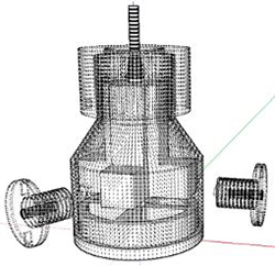
In every brushless DC motor, there are a few common parts: the rotor has a few powerful magnets embedded in it, a stators with coils of wire, and the an enclosure to keep everything together. [pitrack] printed all these parts off on his Makerbot, winding each of the three coils with about 400 turns of 26 AWG magnet wire. Also embedded in the stator are a trio of hall effect sensors to make the control via an Arduino and an L6234 motor driver easy.
For his next trick, [pitrack] is going to test the efficiency of the motor and attempt to optimize it. In the long term, it should be possible to parameterize the design of one of these printed motors, effectively allowing anyone to type in the torque and Kv rating of a desired motor, plug that into an equation, and have a motor design come out the other end.


This is a fantastic idea, it won’t be very efficient though and probably not usable in high-power applications.
You could also try making asynchronous motors with this technique or try making a sensorless synchronous motor.
I really like the way magnets are inserted during printing, it shows forethought, something I often see lacking in projects today. The design can be improved quite a bit and I really hope to see the parametric design tool for this.
My least favorite part; Typoes:
“…a stators with coils of wire, and the an enclosure…”
Otherwise nice job and thank you!
My least favorite part; Grammar-Nazis that can’t spell:
“Typoes”
Awesome hack! Combine this with the servo stock project and reprap just became a whole lot more reprapy. Servo-stock uses PID control with indexing and dc motors to replace stepper motors. Could be really cool.
Might be a good idea to drop an extra ‘p’ in there.
Not sure how long plastic lasts as bearing material, he could get some bearings and insert them as he prints like he did the magnets, alignment could be tricky, nice build.
Nylon could wear pretty well, should work pretty well as a bushing. I have heard heat is an issue with high power motors so that would be interesting to look at.
Would floating magnetic bearings be possible? They’re great where they’re used, but presumably they’re tricky and that’s why we don’t see many of them.
Every once in a while you see something that really embodies the original promise of 3D printing. I can’t imagine a better way to learn the physics of a brushless motor, and he’s made an otherwise fairly involved task seem almost trivial. With the ease of parameterisation, I can see some enterprising students taking this making some science fair projects that would blow my middle school coil motor out of the water. Can’t wait to see some traces of coil current and Hall effect output – or the effects on torque and speed that adjusting phase angle produces. Also, I expect we’ll see his next video end in a quad copter flight.
400 turns AWG 26 per winding sounds an order of magnitude too high for battery operations. That’s probably a mechanical limitation on the machine on how thick the wires can handle.
For reference, this gives you an idea what’s needed for winding your own BLDC motors for RC airplanes.
http://www.flyelectric.ukgateway.net/motors.htm
>More power/speed than a 400: 6 minutes at full throttle on 8xAR800’s. 16 turns of 2 strands of 0.375mm wire. 14.5A static @ 15,600 RPM with RC2400’s
So don’t expect to use this to build the motor for quadcoptor or RC race car. Have fun building this.
When the motor is spinning, it is simultaneously acting as a motor and a generator, and the faster it turns the higher the backwards EMF from the coils until it reaches parity with the voltage source and the motor can gain no more speed.
The RC motor’s coils are effectively just a short circuit as far as the battery is concerned, but it is spinning at 15kprm which means even with so few turns of wire, there’s actually effectively only a fraction of a volt acting across the coil and that limits the current. If you tried to have 16 turns of wire in a stepper motor going nearly 0 rpm, it would turn into smoke in about five seconds.
Same effect can be had if you stall your RC plane motor in a vice and apply full power. Depending on your battery pack, it pretty much goes *puf*
Because of the # of turns, it doesn’t take a whole lot of RPM before the back EMF reaches the external voltage. i.e. the top speed of the motor will be very slow on batteries as you would need a higher voltage to get higher speed.
The RC motor (cars/planes) all have very few turn to get high RPM at battery voltage.
Theoretically, you can reach infinite speed if your load is exactly zero, including bearing friction, since the motor is “externally” commutated. You can always increase the switching speed but you’ll just get lower and lower torque out of it because less and less current can flow through the coil. You never actually reach the top speed, which in terms of 16 versus 400 turns in a coil is probably something ridiculous.
The # of turn would increase the inductance and you’ll need a very high voltage to be able to pump current (torque is dependent on current) into the motor. Just cranking up the switching speed means that the impedance of the winding would go up as well, so even lower current.
It would, but with just 400 turns of wire, the impedance is the least of your worries.
The motor won’t reach infinite speed.
From Wiki: Motor_constants
>Kv is the motor velocity constant, measured in RPM per volt (not to be confused with kV, the abbreviation for kilovolt).[2] The Kv rating of a brushless motor is the ratio of the motor’s unloaded RPM to the peak (not RMS) voltage on the wires connected to the coils (the back-EMF).
>e.g., winding a motor with 6 turns with 2 parallel wires instead of 12 turns single wire will double the velocity constant, Kv,
>Once the motor’s rotational velocity is such that the back-EMF is equal to the battery voltage (also called DC line voltage), the motor reaches its limit speed.
More turns means your coil pick up higher voltage at the same RPM.
Back EMF = 2 * B * L * r * w * N where L = length of loop, r = radius of loop, w = rotational speed, N = # of turns
The only way you could get the motor speed up is to decrease the magnetic field. That’s why motors with electromagnetic field windings can get out of control if the winding were to be disconnect..
It’s possible to do field weakening by adjusting the phase of the applied magnetic field.
Precisely. Since these aren’t brushed DC motors with fixed commutation timing, you can get them to run faster and faster in principle to infinity at the expense of losing power and torque.
Of course they won’t run at megahertz switching speeds in reality, but that’s beside the point.
Phase timing or “field weakening” is also the method employed in electric cars to get the motor to work near 0 mph without changing gears, because you can’t gear the motor for 120 mph at top speed and then drive in rush hour traffic. Instead, you gear for lower speeds, and then “overspeed” it to get the nominal range that you print on the advertisement.
Neat project. I built a black motor in college and my design was limited by the manufacturing techniques I had. The printer lets him do what ever he wants. As far as power and efficiency my guess is that the missing back iron is going to be a huge limitation.
Magnetic flux flows in a circuit from the north pole to the south pole kind of like electricity it can encounter resistance (called reluctance) in the circuit. A good magnetic steel is about 3000 times lower reluctance than air (or plastic)
It won’t hurt the efficiency of the design, but it will cause significant loss in torque.
On the other hand, with less hysteresis (iron loss), the motor may be more efficient, and due to the lower impedance of air core coils, it can turn a whole lot faster. That’s why the power isn’t hurt either – it is just shifted up to higher speeds.
Beautiful hack, but I don’t think it has any practical value.
BLDC motors are all about accuracy & tolerance. The air gap between the stator electromagnets and the rotor magnets should be as small as possible to minimize flux loss. Even if you get tight initial tolerance, you will have to enlarge those gaps to compensate for the deformation that the (relatively soft) material would experience in high speeds.
I applaud this guy’s effort and ingenuity, but something I noticed from the instructable was that the motor seemed to be an “in-runner” style BLDC – and all the bearing and shaft parts were a part of the printed design.
While I am sure this was the main part of the exercise, in that the goal was to make an “as-completely-as-possible” 3D printed motor, the design could potentially be improved by going with an out-runner style, and using hard parts for the shafting and bearings.
The rotor could be one piece (very similar to his current stator) – with the magnets on the inner surface. A bearing or two could be press-fitted (and/or secured with epoxy) to the end; a second shaft – or simply a “plate” with holes to tap for screws could be added to the end as well for mounting driven components.
The stator could be similar (and look like his current rotor) – with a metal shaft, around which would rotate the new rotor on the bearing; the bottom “cross-piece” (where the coils currently are wound for his rotor could be stepped out and extended to make mounting legs as in existing BLDC out-runner designs. Provision could also be made for the sensors.
This would reduce the printed parts count down to a couple parts – fewer parts is ultimately a good thing (but I can see why more were needed for an in-runner motor – but maybe that could be redesigned as well?).
Print everything in ABS (instead of PLA as is currently being done) for maximum heat absorption capability (?) – though at a certain point you might want to print this on a UV resin printer to be able to use higher temperature-capable materials.
I wonder also if something “hybrid” could be done – that is, part of the motor – maybe the stator – built using a laser cutter, with the rotor printed? Or – could the whole thing be done with a laser cutter (perhaps taking advantage of the laser cutter strengths of flat parts)? Maybe a “thin” motor could be made with layers, bolted together (or otherwise assembled) – using acrylic or other materials could make for a higher-temp motor.
Hmm – or drop that kind of design onto a waterjet…but now you are moving into machining (could also machine it using a CNC mill – and now you are just making a BLDC motor that could be bought cheaper – though the potential for parameterized design is still there, which might make the extra cost worth it for some purposes).
At first thought it was great, but than comes second one which told me: what with heat disipation? Motor cases and parts are not made from plastic due to that reason – you do not want your motor to either melt, or burn, or both.
It would be great tool for teaching.
One of the things they do in some motors is to have a fan blades on the rotor for air cooling. It robs a bit of the torque, but that could be done in the 3D printing.
Don’t you find it funny that these motors with fans are made of metal? In these motors even metal case don’t provide enough heat dissipation. It can be found in probably every electrotechnical book.
They have a fan because the rotor is also heating up due to hysteresis/inductive losses, or the rotor has windings that carry some significant externally applied current (magnetizing current) and there’s no physical contact to anything except at the bearing surfaces, so the rotor would get incredibly hot without air blasting over it.
Actually not. They use metal because it is a strong material, relatively cheap and you want something that doesn’t deform under heat nor the magnetic forces especially if you want to leave an air gap (for the magnetic flux) as small as possible. Plastic is definitely the wrong material for the job.
Air cooling allows you to trade off copper/conductor loss vs efficiency and/or make a smaller motor with higher power. Copper is getting really expensive, so I would expect that to happen more often.
Lots of servos in plastic casings o:
But it’s very limited. If you want something with torque it would be probably fullmetal, have a look at industrial servos.
I thought there had to be an iron stator to help saturate the magnetic field?
Well.. you don’t absolutely need one, but if the solenoids had an iron core the magnetic field could be ~ 3 orders of magnitude stronger for the same current, so it would be much more efficient. I made up for this by using stronger magnets than they typically do in motors, and driving more current.
Effective – not efficient. Whether you have iron in there doesn’t make it waste any power. It simply makes the motor weaker.
Hey this is pitrack! Thanks for the comments everyone, lots of good thoughts.
Joe is right (although name strator is not too right :) ), and if you really like bldc motors this much you can find on the net calculator which would help you with creating it. Some time ago MIT student made whole DIY electrical mountainboard, including motor, it could be nice start for search :)
Nice project. I have a project where I pause the printer to insert a screen. You to to have edited the program to pause and move. Can you explain briefly how you did this. Or send me to a site where I could understand editing the program better. thanks