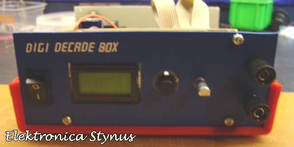
[Stynus] has finished a unique decade resistance box which doesn’t use conventional rotary switches to select the appropriate resistors. These switches are old fashioned and expensive, so [Stynus] built this decade resistance box that uses a microcontroller and a series of relays to switch the resistors.
Simply selecting a resistance on the screen tells the microcontrollers which resistors need to be switched in order to provide the proper resistance. The box uses relays to do switching instead of transistors because the transistors don’t handle high frequency AC as well as the relays. The device is powered by an 18V transformer and rectifier and, as a bonus, [Stynus] got all of his parts on the cheap which made this a great solution to the expensive resistance decade box problem.
This is a very well-polished piece of test equipment. We’ve featured other decade resistance boxes but never one that was controlled by a microcontroller. All of the PCB layouts and the code for microcontroller are available on the project site if you have a desire to make your own.


I like the design I would imagine all those relays to be expensive too. Perhaps a dumb question but would an SCR not work instead of a relay?
Those are ultra cheap Chinese relays. Less than $1 each.
Whoops, these are about $1.52 each, Japanese ones. Still, not too bad for 12 of them.
The ubiquitous blue “Songle” brand relays can be had for $0.13 each on Taobao.
Yes the multi switch is only $3.50-5.00 in most houses. I think he was just being difficult or HaD is looking at Rat Shack prices lol. Anyway, nice design with the usual overkill needed to show off :)
Thumbwheel switches like the ones used in this old design (which I copied myself):
http://hackaday.com/2012/08/21/building-a-resistor-substitution-decade-box/
can be bought cheaper than an array of relays and a microcontroller, while still allowing you to set an exact resistance number (and pretend it’s accurate).
I can imagine uses for having a microcontroller in one of these though. For one thing you could keep a set of resistances in memory to avoid having to dial them in each time. Also, by adding current monitoring, and getting the microcontroller to do a little math, you could create an AC current/voltage regulator. Albiet with a rather poor response time.
Yes, that last point would be the best reason for doing this. Actually I’ve got about 50 relays sitting around (although anly about six less than 10V), I’d be tempted to give this a go if I had the time.
If by AC you mean the general sense of arbitrary waveforms, sure. If you mean 50/60Hz sinusoids such as mains power, a stepper or hobby servo turning a variac seems like a more practical way to let a microprocessor regulate power.
It would be neat if instead of using relays, he actually had a synthesized resistance in the decade box (by having a load that sunk a current for a given amount of voltage). A lot of calibration equipment for multimeters use this technique; you can ramp it up to higher-than-metrological power. The only problem I can forsee with that is frequency response after a point, but that is always an issue with decade boxes (and, I suppose, voltage handling, but…what are you doing with a decade box for that?)
The main problem I see would be that building such synthetic sources and then characterizing and calibrating them would be more difficult and expensive than buying a bunch of rotary switches or relays.
I mean, I have a multimeter. This just uses Ohm’s law (with an ADC & DAC). It could certainly be better than 1% (plus relay tolerance) like this box, particularly because you don’t stack the tolerances.
Relays are cheaper than switches? I guess with the right ones… Nice work, though!
Is there any way to compensate for the added resistance of the relays. If one relay is used, it adds X ohms. 12 relays adds 12X.
This would vary with many parameters, including the applied current and past applied currents. If he knew he kept his currents below a certain amount, and used gold contact relays, you could estimate something roughly. Silver-contact? Hoo boy.
This is why test equipment uses reed relays (which can’t carry much current, but are hermetic.) Heck, mercury-wetted are even better.
This seems like a good application for a digital pot.
A typical digital pot has two limitations that people tend to overlook: First, the tolerance is horrible. Second, the power rating is quite bad. I didn’t check, but I’d say this project beats an ordinary digital pot in both aspects, and the resolution is most likely better also.
Digital pots max out at about 1024 “steps” although 512 or 128 are much more common but the current rating is terrible.
Easy, just use 100 or so in parallel. :)
It would even work out cheaper at this price (ignoring PCB etc.):
http://www.rockby.com.au/catresultssQL_12.cfm?Searchkey=digital+pot&stock_no=41464
And….. most digital pots only allows voltages falling in range of their own vdd.
Like the datasheet for MCP4011 says “Absolute Maximum Ratings: A,B and W terminals w.r.t VSS…… -0.3V to VDD + 0.3V”
Since when are transistors unable to handle switching AC current?
Someone should let the radio industry know that the millions of solid-state transceivers sold over the last few decades don’t actually work…
Exactly my thought, transistors are way, way faster then relays lol. Maybe they mean something like relays can handle transients better? Bit far fetched though.
It’s really more of a BCD resistance box, isn’t it?
Of course, you could also make a binary resistance box — it would save a whopping 2 relays per three decades (10 instead of 12), along with their contact resistance.