[Alex] needed a project for his microcomputer circuits class. He wanted something that would challenge him on both the electronics side of things, as well as the programming side. He ended up designing an 8 by 16 grid of LED’s that was turned into a game of Tetris.
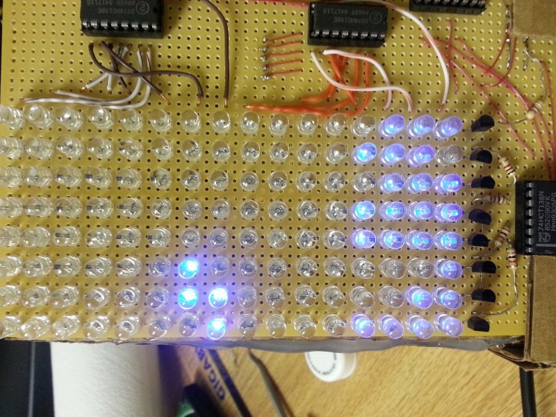
He arranged all 128 LED’s into the grid on a piece of perfboard. All of the anodes were bent over and connected together into rows of 8 LED’s. The cathodes were bent perpendicularly and forms columns of 16 LED’s. This way, if power is applied to one row and a single column is grounded, one LED will light up at the intersection. This method only works reliably to light up a single LED at a time. With that in mind, [Alex] needed to have a very high “refresh rate” for his display. He only ever lights up one LED at a time, but he scans through the 128 LED’s so fast that persistence of vision prevents you from noticing. To the human eye, it looks like multiple LED’s are lit up simultaneously.
[Alex] planned to use an Arduino to control this display, but it doesn’t have enough outputs on its own to control all of those lights. He ended up using multiple 74138 decoder/multiplexer IC’s to control the LED’s. Since the columns have inverted outputs, he couldn’t just hook them straight up to the LED’s. Instead he had to run the signals through a set of PNP transistors to flip the logic. This setup allowed [Alex] to control all 128 LED’s with just seven bits, but it was too slow for him.
His solution was to control the multiplexers with counter IC’s. The Arduino can just increment the counter up to the appropriate LED. The Arduino then controls the state of the LED using the active high enable line from the column multiplexer chip.
[Alex] wanted more than just a static image to show off on his new display, so he programmed in a version of Tetris. The controller is just a piece of perfboard with four push buttons. He had to work out all of the programming to ensure the game ran smoothly while properly updating the screen and simultaneously reading the controller for new input. All of this ran on the Arduino.


Nice logic progression
Agreed, nice use of hardware bits. I can definitely appreciate the “doing it for the challenge” aspect, as opposed to easier methods. I think you learn better that way :)
After reading all the response to the Arduino KIM emulator thing, I’m staggered by this!
In case none of you have ever seen the circuit for a KIM-1, SYM-1 or AIM-1, this is pretty much how we did it “back in the day”
with or without counters, usually without, just incrementing the value in the 6522 VIA output register.
On an Arduino if you’ve got an 8 x 16 grid, I’d use a 74xx138 for the columns (x) and a 74xx154 (y) for the rows, that’s 7 bits, 3 for the columns (x), 4 for the rows (y)
Just one more reason to go for a Mega!
I like it, nice job!
I’m a bit of a noob, so forgive me if I’m being dumb, but couldn’t your frame buffer have been implemented in 16 bytes (albeit with a lot of bit twiddling)?
I thought abou using a single bit per pixel, however this woulf have wasted a pot of cpu time to shift the right bit out of each byte.
No, you need to shit a mask byte once per scan line, then perform a logical AND to extract the column bit. The CPU cost for this is tiny (call it 20 clock cycles per complete scan, or a bit more than 1 millionth of a second on an AVR).
The 74HC595 is a latching shift register which is SPI com Patti. You can shift out frames pretty fast that way, especially if you use a micro with some kind of DMA and hardware to control the latching/rows.
Or use 16 chips, they’re quite cheap.
That’s how I built an 8x8x8 LED cube. An arduino outputting 8 bytes (1 layer) at a time with the SPI peripheral is fast enough to do pov across the 8 layers with 8 bit pwm and calculating display animations at the same time.
com Patti is my predictive keyboard’s way of spelling compatible…
There are a number of different ways of doing this. 8×16 can be done with 3 x 74xx595s, or a TLC5940 plus a 595 (the 5940 can PWM 16 LEDs at a time, use the 595 to select the column) or a couple of MAX7219 (which can drive an 8×8 matrix each).
I think it could be possible to use something like two counter chips to count the clock pulse and select the column automatically, then you just keep shifting out your entire framebuffer out using SPI.
The Maxim chip is pricey, though there is the HT1632C which can drive 256 LEDs – but has no western suppliers.
Couldn’t you light up one row at a time?
So what is the maximum number of LEDs that can be used before the persistence of vision effect breaks down? I mean could this technique be used to display primitive video if it had enough LEDs?
I’ve though about that, and I’m not sure what the answer is. I think that adding capacitors to hold a charge on each led could drastically reduce the required refresh rate and help bump up the resolution. I’ve seen a lot of custom displays (animated billboards, stadium screens, etc) that are big RGBLED matrcies, but I doubt they’re straight POV.
Wouldn’t adding caps also create a bit of a delay as they charge? If so, do you think that it would be a problem?
Fantastic build, by the way.
For the shift register questions, there are a two main reasons why I went with straight POV:
1. It takes a lot longer to assemble shift in a piece of row data than it does to just increment a counter. Granted, my refresh rate could have been eight times slower, but this way keeps the code nice and simple.
2. I already had the counter and demux ICs on hand.
How about using a counter for the row select, and then write a whole row of bits in one time through an 8 bit output port ?
That would bumped up the number of required IO lines without much real improvement in program requirements
Why is there no video demo?! :(
here ya go!
https://www.youtube.com/watch?v=nYfAjwWjQ2g&feature=youtu.be