
Filters and Drums
Logic Noise is an exploration of building raw synthesizers with CMOS logic chips. This session, we continue to abuse the 4069UB as an amplifier. We’ll turn the simple unity-gain buffer of last session into a single-pole active lowpass filter with a single part. (Spoiler: it’s a capacitor.)
While totally useful, this simple filter is a bit boring and difficult to make dynamic. So we’ll look into an entirely different filter, the Twin-T notch filter, that turns out to be sharp enough to build a sine-wave oscillator on, and tweakable enough that we’ll make a damped-oscillator drum sound out of it.
Here’s a quick demo of where we’re heading. Read on to see how we get there.
Filters
Last session, we built an amplifier and played around with the gain: the ratio of how much voltage swing is output relative to how much is input. An active filter is an amplifier where this gain depends on the frequency of the incoming signal. This lets us carve out different frequency ranges that we’d either like more or less of. (In general, though, you don’t need an amplifier to filter. See passive filters versus active filters.)
When you pluck a string on a guitar, for instance, all sorts of frequencies are produced. But over time the string vibrations are damped out by the wood that the guitar is made of, and within a half-second or so, most of the vibrations left are related to the string’s fundamental vibrational frequency (determined by where your finger is on the frets). The higher frequency vibrations are the first to go. This suggests a sound synthesis strategy to make “natural” sounding instruments: generate all sorts of frequencies and then filter out the higher ones.
Single-pole Lowpass Filter
Given that we’ve already made a few simple amplifier circuits last time, it’s a quick step to understand the simplest of all filters: the single-pole filter. Here’s the circuit diagram:
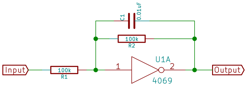
Yeah, that’s an added capacitor. That’s all there is to it. But have a listen to the difference:
Remember the intuition about the negative-feedback amplifier from last time. We had two resistors, one between the input and the 4069, and the other in feedback between the (inverted) output and the input. When the input voltage wiggled around the 4069’s neutral voltage, the output wiggled in the opposite direction. And the ratio of the voltage swings, the gain, depends on how hard the feedback path has to work to cancel out the incoming signal current.
The same intuition works for the filter, as long as you understand one thing about capacitors. Capacitors pass current through them only reluctantly. The amount of current a capacitor passes before it’s “charged up” to a voltage that resists any further incoming current is referred to as its capacitance. Or, in electro-math: C = Q/V or V = Q/C, where Q is the charge on the capacitor, which is also the current (charge per second) summed up over time.
In short, the more charge you put into a capacitor, the higher voltage it develops to resist putting more charge into it. And how quickly this voltage ramps up is proportional to one over the capacitance and directly proportional to the current passing through.
For us, this means that it’s easy to pass a given current through a capacitor for a short while, harder to pass the same current through for a longer time, and impossible to get current through forever without increasing the input voltage to overcome the capacitor’s “charged-up” voltage. Or put another way: capacitors let high frequency current vibrations through easily, resist middle frequencies, and deny constant-voltage direct current.
So what happens when we put a capacitor in the feedback path of our unity-gain feedback amplifier? Since the capacitor nearly blocks very low frequencies, all of them have to pass through the resistor, and we get unity gain. As we increase the frequency, some of the current starts to pass through the capacitor and the total feedback resistance is lowered. This means that the output has an easier job cancelling out the input, and thus less gain at middle frequencies. At very high frequencies, the capacitor will pass currents so easily that almost none will even need to go through the resistor, and the gain drops even lower.
Put more succinctly, the capacitor resists lower frequencies more than higher ones. In a negative feedback amplifier, output gain increases when it’s harder to push current through the feedback path. So by putting a capacitor in the feedback path, we make an amplifier with more gain in the low frequencies and less gain for higher frequencies. Voila, a lowpass filter!
Variable Cutoff Lowpass Filter
What if we want to vary the cutoff frequency? In math, the cutoff frequency for a single pole lowpass filter like this is 1/(2 * pi * R * C). Practically, we can vary the cutoff frequency by changing the capacitor or by changing the input current through the resistor. So we’ll set the basic range by picking a capacitor value and vary the filter’s frequency response by turning a potentiometer. For the circuit here, the cutoff frequency ranges from 160 Hz at 100k ohms to 1600 Hz at 10k ohms.
But there’s one catch with varying the input resistor; we also change the overall gain which depends on the ratio of feedback resistor to input resistor. So if you’re going to be changing the frequency response by changing the input resistor a lot, you might also want to change the feedback resistor at the same time to track it, holding the overall (passband) gain roughly constant. For that, you’ll need a stereo / dual potentiometer, which is simply two potentiometers linked to the same shaft. With one knob, you control two identical resistors.
Before we leave the single pole filter, you can convert the lowpass filter here into a highpass filter simply by moving the capacitor out from the feedback loop and sticking it in front of the input resistor. Give it a shot!
Twin-T Filter
Our story gets significantly more interesting if we toss a more complicated filtering element in the feedback path, and one of our favorite filters is the Twin T. Instead of being a lowpass filter like the one above, the Twin T is a notch filter. Notch filters pass both high and low frequencies, but are tuned to knock out a particular frequency in the middle.
In its raw form, the Twin T filter is fairly useful for killing a specific nuisance frequency in a signal. Maybe you want to knock out power line noise (60Hz in the USA, 50Hz in Europe). Toss a Twin T filter that’s tuned to 60Hz into the chain, and you’ll get rid of most of the noise without damping down the rest of your signal very much. To see why it’s called a Twin T, have a look at the circuit diagram:
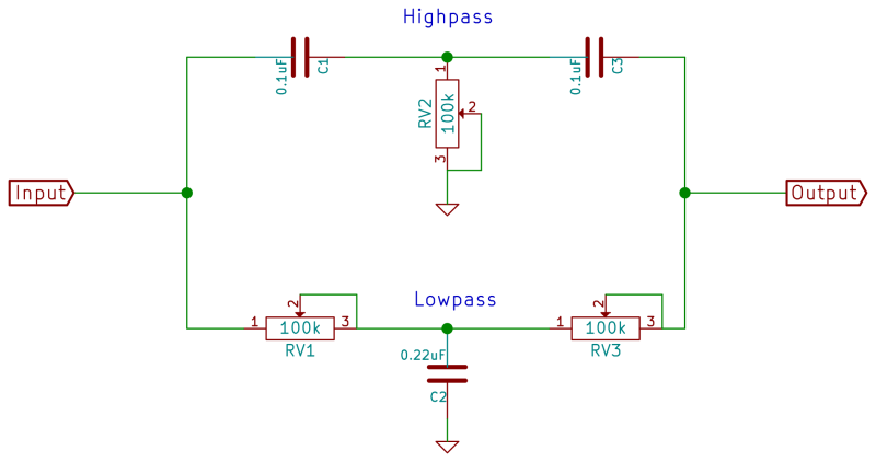
The Twin T works by combining two signal paths, each one T-shaped. The T with two resistors and a capacitor to ground is a simple lowpass filter, essentially a passive version of the one we made above. The other T with the series capacitors and resistor to ground is a highpass filter.
Highpass and lowpass sounds like everything should get through, right? Yes, but. At the frequency that the filter is tuned for (the “cutoff” frequency) the two outputs are exactly 90 degrees out of phase from the input, but in opposite directions. In theory, if both Ts are tuned to the same frequency the two paths exactly cancel each other out at the cutoff frequency and none that cutoff frequency makes it through at all. In reality, you can actually get the two branches fairly close to each other and get very good, but not perfect, cancellation of the tuned frequency.
What happens when we put a Twin T filter into the feedback path of an amplifier? Remember that the negative feedback logic requires the output to create more voltage the harder it is to push current back through the feedback path. So instead of knocking out the frequency that the filter is tuned to, we get that one particular frequency amplified. If there’s a little bit of noise entering the input at our tuned frequency, it’ll get amplified a lot and all of the other frequencies will get attenuated. And suddenly you’ve got a sine-wave oscillator.
Drums
Which brings us to today’s killer circuit, and a little bit of a refinement on the above explanation. The short version is that we detune the Twin T filter a little bit so that it only rings when it’s given an impulse and then dies out.
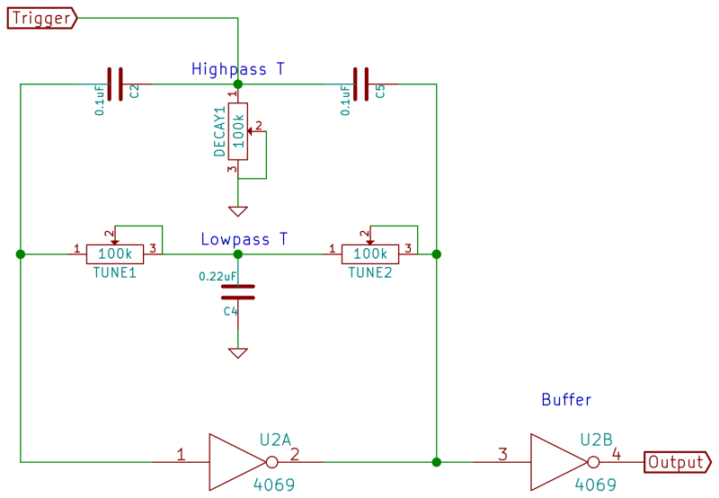
First let’s play a little bit and build up the Twin-T and 4069UB amplifier part of the circuit. It’s just the Twin-T filter from above set up in the feedback path of a 4069UB inverter stage, and then sent out directly through another 4069UB inverter as a buffer. It’s overdriven and you’ll hear the clicks of the trigger bleeding through, but it’s a start.
Refinements
With the basic circuit working, let’s expand on it in two different ways. First, we’ll drive the drum with another oscillator circuit. Then, we’ll pass the audio out through a lowpass filter to knock off some of the trigger pulse bleedthrough.
Here’s the final circuit:
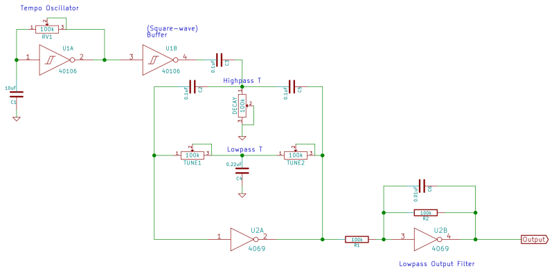
Starting on the left, we have a very low frequency oscillator set up on the 40106 and buffered using another 40106 stage. This simply puts out a nice reliable square wave. The signal then passes through a capacitor, which again has the effect of letting only the higher frequencies pass through. What makes it through looks basically like a quick pulse (in green).
The trigger signal pulse is inserted into the feedback loop of the Twin T. It’s actually not crucial where you attach the trigger, but it’ll couple less with the Twin T section if you connect it here.
And finally, we’ll pass the signal through a lowpass filter to remove the clicky noise that comes from the raw trigger signal feeding through to the output.
Range
What values should we use for capacitors and resistors? Try to pick the component values so that the single capacitor in the lowpass T is twice as large as the two capacitors (2 C) and the single resistor is half as large as the paired resistors (1/2 R). This makes both Ts tune to the same frequency, given again by 1/(2*pi*R*C) where R and C are the values of the paired resistors and capacitors respectively.
In practice, try to get factor-of-two capacitors and leave the resistors adjustable wherever possible. Since we’ll be de-tuning the circuit on purpose to make the oscillations die out slowly, there’s not a reliable formula for the resistances. You’ll just have to pick capacitors and tweak the knobs until it works. That said, if you find you want frequencies outside of the range that you’re currently getting, don’t hesitate to swap out the capacitors.
Tweaking and Tuning
Detuning the Twin-T section is the secret to making this circuit work as a drum rather than as a sine-wave oscillator, and the approach you’ll have to take is a bit experimental, so let’s talk about tuning this circuit. If you align the two halves of the Twin T perfectly, as we mentioned before, only the one single frequency will be blocked, and thus only that one frequency will be amplified by the negative feedback circuit. You’ll get a very nice sine wave oscillator, but not drums.
If you detune the two halves of the Twin T from each other, especially if you do so by raising the cutoff frequency of the highpass filter so that it’s higher than the lowpass filter, a wider and wider band of frequencies are blocked by the Twin T, and thus receive the extra gain from the amplifier.
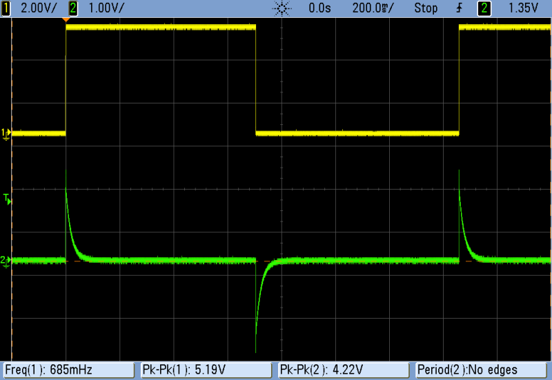
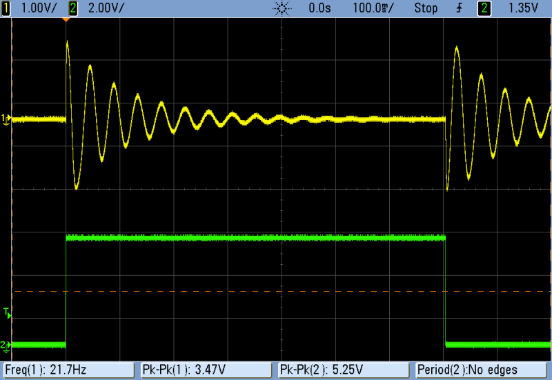
But as you spread the gain over a wider and wider band of frequencies, you get less gain at any given frequency. As you continue to detune the Ts from each other, you’ll reach a point where the circuit no longer amplifies any single frequency enough to oscillate indefinitely by itself. However, and this is the key here, the filter will oscillate for a while if you provide it with a strong enough impulse signal. And that’s exactly what we’re doing with the square wave coupled through the capacitor coming from the tempo oscillator. It’s nice to watch the damped waveforms on a scope if you’ve got one.
So here’s a procedure for getting close to your desired sound. To enable oscillation over a wide range of frequencies, set the decay potentiometer as low as it will go. This sets the highpass leg of the T to a very high cutoff frequency, which means that it’s passing nearly nothing. This frees up the lowpass T section to determine the pitch, and for most of the tuning potentiometer’s range you’ll get oscillations. Pick the rough pitch you want by listening to the oscillator. Now you can tune up the decay pot until the oscillations are just damped out and you’ll be set.
But notice that the two potentiometers influence each other a little bit. That’s because the two legs of the T are simply electrically connected. So as you increase the decay to go from oscillator to drum, be ready to also tweak the frequency potentiometer to keep the drum tone at your desired pitch and decay rate.
Extensions
If you’re interested in exploring more active filter designs than just the single pole lowpass shown here, have a look at Rod Elliott’s great writeup on active filters. You can either break down and use op-amps and dual power supplies, or you can keep hacking and replace any of the op-amps in his circuits with a 4069UB stage as long as they only use negative feedback and have the op-amp’s positive terminal connected to ground. In particular, have a look at the multiple feedback topology and the biquad.
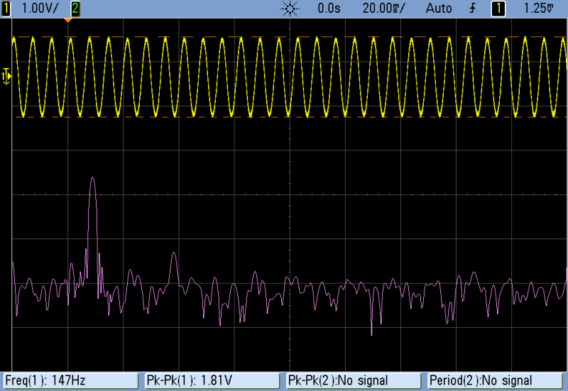
If you don’t need synth drums, you can simply tune the Twin T up and use the circuit as a sine wave oscillator. For a single set of capacitors it’s not very widely adjustable, but if all you need is a single frequency you can pick the right capacitors and you’re set. It’s not the best sine wave oscillator out there, but it’s hard to beat a one-chip build with a few passive components thrown in.
But don’t take our word for it: here’s a scope shot. The yellow line is the produced sine wave, and the purple is a FFT of the signal. Vertical bars are 20dBV, or a factor of ten. The first peak, at 150Hz is our sine wave, and the second peak is down in voltage by about a factor of 100. It’s not lab equipment, but it’s pretty solid for the abuse of a CMOS logic chip.
And there’s nothing stopping you from feeding the circuit with audio-frequency trigger pulses if you want to freak out. The result is very similar to the sync oscillator we built before but it’s a lot mellower because the waveforms involved are fundamentally sine waves here.
Have fun!


Truly enjoy this series. Keep it up!
great project !!
Reminds me of the old days with hacking on CMOS logic
I always look forward to each of these!
Very nice series, keep up the great work!
Great series, great sounds, great quality content!
Cool stuff! Now we’re really getting somewhere, transcending “noise” territory. Bass drum sounds great, very 808-ty. I’d love to implement pitch envelope to get snappier attack. How would I go about that?
Have a look at the service manual for the 808 if you’re serious. Oh heck, have a look either way, because the 808 is a classic bass drum. The circuit is on the right-hand side of page 9.
In the center of the circuit is an op-amp (Pins 1,2,3 of IC 12) with one T from a twin-T in its feedback loop (C41, C42, R166, R165). Instead of a variable resistor to ground, as we used, there’s a transistor (Q43) between the resistors to ground. When this transistor is on, it shorts out one of the resistors (R165) making the effective resistance lower, and the pitch higher.
Then envelope for all that must be in the Q41/Q42 branch that leads into that, but I’m just looking the schema over now, and I’ve never built it. My guess is that the capacitor (C38) is charged up suddenly on a trigger event and slowly bleeds out through Q42, which in turn opens up Q43 to raise the pitch. (And additionally sends a pulse on through to the decay / volume envelope at the other op-amp on IC 12.)
But yeah, as long as we’re working through this, capacitor C40 is just like the cap we use to pass the trigger pulse through, only they use a diode (D53) so that it only triggers on the positive-going flank of the input rather than both as we did. All that stuff to the left of C40 is input-conditioning for triggering and voice selection. BD set high enables the bass drum which plays on the common trigger.
The last bit from R171 through Q44 looks like an amplifier and passive lowpass filter (C48 & R175) to knock off some of the click. Not unlike what I ended up doing with the lowpass filter on our example.
I should really build this up. Oh man, there’s a brief overview of the circuit on the bottom of page 5 that I didn’t notice until I wrote this post. TLDR read that instead of my description. They don’t make service manuals like that anymore….
MIL-STD-202F, Technique 213B Cond.
haha, i have run across this series again! many thanks for great explanations. i came to this in a roundabout way by looking up the 808 drum circuit and then trying it, semi-failing and googling around looking to try again. i made a bridged T circuit with the TL072 IC based on 808 schematics and people discussing that. and just fiddled with it without fully understanding what was going on (results here: https://www.youtube.com/watch?v=LLK7r4GY7NM). had issues with the triggering which was cobbled up with a 555 timer, and i used my own amp to cheat in a low pass filter. but i’ll try building it up again from scratch. would love to have a little cheap and even vaguely useable drum module from a few parts.
Hi, thank you for this very effective post. I wanted to present to you the result of my little Twin-T Drum module created from your schematics and videos. A big thank-you!!
the video here: https://www.youtube.com/watch?v=_COKTgpanbA
see you!
Awesome sounding demo. I’m just now re-visiting this circuit — making a combo board with this drum and the cymbals from another section.
I wish I knew a way to make adjusting it less “tweaky”. Like if there were a 3-gang pot to adjust the pitch, and then a smaller pot in series with the single one to vary the detune between the T branches…
Anyway, glad it’s working for you!
Hello Elliot, I’m doing simple step sequencer with drum sound and saw/square oscillator for my physics class in order to get best possible mark (need it to continue education in direction that i want) and i decided to add this as one of the drums.I had tried to build this simple circuit about 4-5 times and none of them works properly- most of them just oscillate without triggering, decay pot do not work (tried to replace it and still not working) or they just do not work at all- I troubleshoot them for loooong time, each one of them, (one of them even killed my potentiometer :/) and i have no clue what I’m doing wrong, I really need your help because deadline is in the next week and I cannot find anything better than this.
i love this!!! also the filter article link by rod elliott is dead, but i think this is a link to what the author was referring to. http://sound.whsites.net/articles/active-filters.htm
Hi Elliott, I’ve really enjoyed making this – so much that I’ve tried to make a ‘drum kit’ with several twin T filters. I have a problem when combining them though: there seems to be ‘cross talk’ in that one twin-T seems to be affecting the sound of the others. Have you any idea what I’d need to do do to keep the signal paths separate?
The Wayback machine comes to the rescue
https://web.archive.org/web/20100414105726/http://sound.westhost.com/articles/active-filters.htm
If it wasn’t for your comment I would never knew about this series. THANK YOU!
The newly developed closed-loop energy-free HVAC is game-changing saving up to 85% of HVAC energy consumption and tonnage; the inspiration for the interchangeable core-cell development came from the bumble bee and their honeycombs which have remarkable strength and high surface area.