Logic Noise: Filters And Drums

Filters and Drums

Logic Noise is an exploration of building raw synthesizers with CMOS logic chips. This session, we continue to abuse the 4069UB as an amplifier. We’ll turn the simple unity-gain buffer of last session into a single-pole active lowpass filter with a single part. (Spoiler: it’s a capacitor.)

While totally useful, this simple filter is a bit boring and difficult to make dynamic. So we’ll look into an entirely different filter, the Twin-T notch filter, that turns out to be sharp enough to build a sine-wave oscillator on, and tweakable enough that we’ll make a damped-oscillator drum sound out of it.

Here’s a quick demo of where we’re heading. Read on to see how we get there.

Continue reading “Logic Noise: Filters And Drums”

Universal Active Filters part 2 for Hackaday by Bil Herd

Universal Active Filters: Part 2

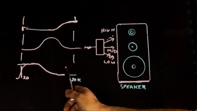
An easy way to conceptualize active filters is thinking about audio speakers. A speaker crossover has a low-pass, high-pass and band-pass effect breaking a signal into three components based upon frequency. In the previous part of this series I took that idea and applied it to a Universal Active Filter built with a single chip opamp based chip known as the UAF-42. By the way, it’s pretty much an older expensive chip, just one I picked out for demonstration.

Using a dual-ganged potentiometer, I was able to adjust the point at which frequencies are allowed to pass or be rejected. We could display this behavior by sweeping the circuit with my sweep frequency function generator which rapidly changes the frequency from low to high while we watch what can get through the filter.

In this installment I’ll test the theory that filtering out the harmonics which make up a square wave results in a predictable degradation of the waveform until at last it is a sine wave. This sine wave occurs at the fundamental frequency of the original square wave. Here’s the video but stick with me after the break to walk through each concept covered.

Continue reading “Universal Active Filters: Part 2”

Universal Active Filters Part 1

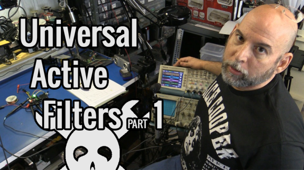
Universal Active Filters: Part 1

Today I am experimenting with a single chip Universal Active Filter, in this case I made a small PCB for the UAF-42 from Texas Instruments. I chose this part in particular as it facilitates setting the filter frequency by changing just a pair of resistors and the somewhat critical values that are contained on the chip have been laser trimmed for accuracy. This type of active filter includes Operational Amplifiers to supply gain and it supports various configurations including simultaneous operating modes such as Band Pass, Low Pass and High Pass make it “Universal”.

Filter Basics

Speaker Crossover Example

Looking at the block diagram you can see where I have inserted a dual-ganged potentiometer to change both resistors simultaneously which should allow a straight forward adjustment for our purposes here.

Looking into the components of a simple RC filter which can easily implement a simple Low Pass or High Pass filter, we see that the math is fairly straight forward and swapping the components with each other is all that is needed to change the type of filter. Continue reading “Universal Active Filters: Part 1”

Open Source Power Line Communication

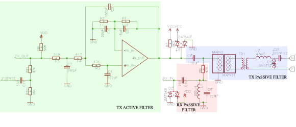
Power Line Communication Filtering


Since we all have wires running throughout our houses to provide mains power, there’s a number of devices that piggyback on mains lines for communication. For his thesis project, [Haris Andrianakis] developed his own power line communication system.

The basic principle of the system is to inject a signal onto the power lines at a much higher frequency than the 50 or 60 Hz of the AC power itself. Using both active and passive filters, the signal can be separated from the AC power and decoded. This system uses frequency-shift keying to encode data. This part is done by a ST7540 modem that’s designed for power line applications. The modem is controlled over SPI by an ATmega168 microcontroller.

[Haris]’ write up goes into detail about some of the challenges he faced, and how to protect the device from the high voltages present. The final result is a remote display for a weigh scale, which communicates over the power line. Schematics, PCB layout, and software are all available.