There are a lot of cheap Chinese CNC machines out there with okay mechanics and terrible electronics. The bearings aren’t complete crap, but the spindle of these CNC machines is a standalone PWM controller with a pot to control the speed. This means you can’t control the spindle speed with LinuxCNC or Mach3.
For his Hackaday Prize entry, [SUF] is building a DC motor controller for a Chinese spindle motor that doesn’t use any kind of encoder. The first part of that project is fairly easy; [SUF] has already built a high current driver. The second bit is a little it harder – because these spindles don’t have an encoder, [SUF] will have to read voltage spikes on the motor poles, giving him the RPM of the spindle. From there, it’s a bit of PID code to get this spindle running at a desired RPM and connecting it to a CNC control box.
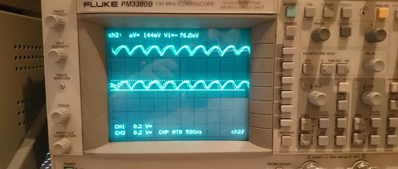
So far, [SUF] has a second version of his board waiting for assembly. In the first version of the board, the switching time for the MOSFET was a little slow, but that’s all corrected in the current revision. It’s a great project to extend the capability of these cheap CNC machines, and perfect project for the Hackaday Prize.


https://www.youtube.com/watch?feature=player_embedded&v=wCjMkMbXvU0
I don’t know what is worse … showing your age by using BC546B’s … god they must have been in the junk box for a while … OR … showing your age by knowing that using BC546B’s is showing your age :S
What is wrong with them? After all, they and 547/8 are all the same mainly up to Vcbo, Vceo and noise figures
Rob: Thank you for your comment on the aging BC546B’s. I’ll change them immediately to BC107 metal cans, even, if I find some great germanium transistors… :-)
Can you please tell me, what is wrong using old parts on a proof of concept circuit? The final one will not have them. If you read the project log carefully you will realize that.
lol I went through my ‘old transistor’ bag the other day and I did see some metal can transistors and even some old five pin dual transistors but sadly I didn’t see any OC97’s
Nothing wrong with it, just having a dig lol. You not alone here as a ‘more experienced’ EE/Tech.
And for those who didn’t get the original joke. Most people would choose the BC546C over the BC546B. The ‘C’ version has been around for over 20 years.
Hi Rob,
Sorry to tell, but the bad assumption is somewhere here. The distinction between the A, B and C models are not the time. This ones are coming from exactly the same era. Even they are not manufactured separately. They are exactly the same components. The only difference between them is the hFE value. The product measured at the factory and as the result of the manufacturing (according to the datasheet):
BC546A hFE 110-220
BC546B hFE 200-450
BC546C hFE 420-800
And, in my circuit I designed it for hFE = 100, so even the BC546A can fit in.
SUF
Instead of driving the gate with a bunch of discretes, get a gate driver IC. They are made for this.
For instance, the IXDD609PI can drive 9A peak current in/out of the gate, and can be switched on with a logic signal. And it’s only $1.75 single quantity from digi-key in DIP8 package.
Beyond a certain current and switching speeds, you’ll ended up using larger MOSFET for gate drivers and have to build gate drivers for gate drivers. Gate drivers chips also has hysteresis input, so they can still switch cleanly if there are some ground bounce issues (due to ground trace inductance).
Note: OP is using a PMOS as a *high side* switch and has level translation. Recommending the IXDD609 *low side* gate drive is a bad suggestion.
[cyberteque] If you don’t accept comment from others, how would you know that what you have might not be a good idea and most importantly the WHY part. From your comments, it doesn’t sound like you have the experience or research enough on the matter.
Yes, thanks for the note. I noticed later that the OP used a high side switch. For a DC motor control, I would use a low side N-type MOSFET, so that’s what I assumed he had done too. In general, N-type is preferred because they have better characteristics.
The 9A is overkill, but I was looking for a cheap DIP8 type, and that one showed up on top.
Hi Artenz,
You right, I would also use low side switching and N-Channel MOSFETs. But..
because of the measurement method, and because the used circuit is closer to a buck regulator than a simple switch, I needed high side switching. If the low side switching would work either, even requires floating power source for the measurement circuit, and level shifting/isolation for the measurement signal. I was considered this solution at the beginning, but finally dropped it.
I used discrete components on two reasons. One is to learn. Learn how the circuitry working. I learned more about behavior of MOSFETs and BJTs from this than I just drop some integrated driver in it. Two finding a drop in driver was not so easy, if I take all of the necessary factors in consideration. It needed high side switching (or even half-bridge), capability to work on 100% duty (bootstrap capacitor design is out of question here), withstand the 48V supply. Finally I found two good candidates: LT1336 ($5.65 single quantity from digi-key – not considered as a cheap part) and A3946 ($3.66). But Digi-Key is not considered as supplier in this part of the world because of the shipping cost.
I’ve source for the Linear chip (not for the Allegro one) for even a little bit more ($7-8) and may try it out later, but definitely not in this state of the project.
SUF
what is wrong with using discrete power transistors????
as for the IXDD609PI driving 9A peak, whoopy chook, what about sustained??
aaaand this is why I don’t bother posting projects here…
You don’t need sustained current to charge/discharge a mosfet gate. It’s like a small capacitor.
MOSFER gate capacitance are charged/discharged in the order of low tens of nano seconds. Yes, you do want to switch that fast because MOSFET power dissipation is the voltage * current integrated over the switching transition. So at some point it get to see like your full supply voltage and load current. Doing that a number of times (i.e. switching frequency) they starts to add up and you ended up using a heat sink for something that shouldn’t.
Asking for substained current implies it is a DC value and it is not like we are driving a bipolar transistor here.
With a discrete gate driver stage, it is extremely difficult to get fast switching times, current capability, and good rail-to-rail drive. Been there, done that.
And yes, since a MOSFET gate is a capacitor, all you care about is peak current drive capability during charging/discharging.
Gate driver ICs are simply so easy to use. A popular type is the UCC37322, which has 9A capability. An added bonus is they have an enable input, so you can shut down all your gate drivers if you need to disable the bridge.
For isolated/half-bridge/full-bridge driving, you get bootstrapped drivers like the IR2110.
As with the video reply at top – what is so bad about adding an encoder to the spindle? You can measure rpm directly, simplifies circuit, etc.
Hi Alan,
No problem with it at all. An optical encoder was my first idea. Even I designed a new 3D printable rotor to the top of the motor with encoder ring and fan blades instead of the shitty vertical blades currently in:
http://www.thingiverse.com/thing:378489
But never built it. The problem is the construction of my CNC machine. There is something like 2mm between the Z-Axis mechanics and the rotor. The optical ring doesn’t fit in. After this failure I was looking for a solution without encoder and found the current one. Anyway it was a great fun to experiment something unusual. :-)
SUF
this would work well with a CNC340 TinyG conversion, using the TIynG for motors and connect this driver to the spindle output, not bad. Looking forward to your progress.