[Carlos] needed an ADC with a 50 nanosecond sample period for his laser lab, that’s 20Msps! (20 million samples a second). While in recent years, commodity ADCs reaching into the low GSPS have become available, integrated acquisition systems are still somewhat expensive. So [Carlos] decided to do what every good hacker does, and built his own solution. His project post pretty much just links to a whitepaper he wrote (PDF) so we’ll try and boil it down for you:
In order to simplify development [Carlos] borrowed a technique commonly used in the first era of digital oscilloscopes, Equivalent Sampling Time.
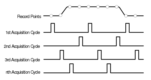
The figure to the right is from the TDS460 manual. While it may seem counter intuitive to those only familiar with modern scopes, the TDS460 achieved a 400MHz bandwidth using a 100MSPS ADC. In order to achieve this the scope acquires a single trace in multiple cycles, each time offsetting the acquisitions as shown and combining the result.
In this way, early digital scope developers could sidestep the limitations of the available ADCs to achieve a higher effective bandwidth. However there is of course one catch: the technique only works for periodic signals.
This was fine for [Carlos] who implemented a technique on a Cypress PSoC 4, which provides analog FPGA-like functionality. By offsetting the ADC trigger he has able to achieve an EST of 48MHz using a ADC sampling at 1MHz. If you want a little help getting into PSOC 4 yourself, check out the guide that [Bil Herd] made.
Neat hack [Carlos] and we hope to hear more about your laser lab in the future.


Glad to see more projects with PSOC’s, they’re great little chips and the IDE is pretty good.
Why does this only work for periodic signals? It looks like it should work for non-periodic as well.
Because they’re only using one ADC, each acquisition cycle assumes the signal coming in is the same as the one before.
Could this not also work for aperiodic signals if there were a controllable delay between ADCs? For instance, if you had available ten low-cost ADCs at 5MSPS and introduced a phase offset would it give you an effective 50MSPS? I’ve been considering something similar using thermal cameras with the introduction of the Lepton because the ITAR 9fps limit is awfully annoying when I want to gather a lot of data but I’m already subject to the 60×80 pixel size.
Yes, that would work. But time-aligning many low-cost ADCs is very complicated to impossible (part of the price tag comes from that), because you’d not only need very specific timing properties on each of the ADCs, but also very finely tuned delay, hence, finely tuned microwave lines on the PCB… next thing you know, you’re designing an 8-layer board, where the PCB alone costs as much as a luxus ADC would have costed.
Also, the author doesn’t have the problem of not being able to get higher rate ADCs — he has the problem of dealing with the data in real time, which your multi-ADC solution doesn’t solve (unless you also make it a multi-CPU solution, in which costs, complexity, reliability and size will start to make a difference).
Got it, I didn’t realize that data capacity was a problem. Also, I thought you could delay the clocks on the ADCs simply by tuning the length of the trace it has to pass through.
You can do that with the trace lengths, but to be honest, in the relevant use cases of this, accuracy is not “amateur” stuff — defining the electrical length of a microstrip line is easy if that line is straight, but will a 90° bend just have no effect? What about tapered bends? Also, let’s say the speed of the wave on that line is 10% speed of light. Then, for your delay to be 1/50 µs would need ummm 60cm of trace. Not really feasible for a single board. Seriously, nowadays, you tackle things like 50MS/s with high enough clock rates — all you really need is something that has a 50 samples deep buffer to get your 1µs observation, and that’s not really hard to implement, on either a CPLD, FPGA, or even using something as simple as discrete shift registers. Furthermore, DSPs sometimes have high-speed serial interconnects [citation needed] or even high-speed parallel interfaces, depending on what your ADC gives you. The Zynq, which is an ARM with a FPGA integrated, might be a nice solution here — just use the FPGA to write samples directly into your CPU cache or DMA them to RAM, and then read them as slow as you want (ie. as fast as your slowish ARM running Linux allows you).
I have seen ADC’s that use the data-out bit clock to control successive approximation sampling. This saves chip complexity and pin count. I don’t know if they will go as fast as you want.
Delays shouldn’t be such a problem that you’re using trace lengths at 5 MSPS. If you do need to worry about trace lengths then there is advanced and FREE software out there to help you. I don’t recall it’s name but it was featured on the BAD Blog. If timing is a problem then use a CPLD/FPGA.
More of a problem is holding the sampled analog signal voltage for the SAR sampling period. Perhaps a bucket brigade.
5MHz (or MSPS) is relatively low speed. 50MHz is getting to the limits of a 2 layer board. 10 of 5MSPS is still 5MHz.
Timing really, really isn’t the problem. .Matching timing is easy. A $30 Artix-7 from Xilinx could deal with lines timeshifted to ~80 picosecond precision, or even ~8 picoseconds if you don’t need tons of different ones. And that’s actually fully calibrated and stable over temperature. So you could easily generate a GSa/s equivalent-time sampler with almost no effort. Even a simple Spartan-6 can do sub-ns precision delays really, really easily.
The problem is analog. You can’t take your input signal and shove it into tons of ADCs for free. Eventually the ADCs start to load down the input signal, and things get very wonky. And that’s not even thinking about the problem of actually fanning out the signal as well.
:) I went to bed and was like “I should have said that you can easily manage, especially with proper hardware (FPGAs)”; then I realized, my post’s point still stands: The real use case of this is higher rate sampling, because, with an Artix7 or even just an older Spartan, who cares that your samples come in at 50MS/s? Just hook up that ADC’s data lines to a set of input ports, write a minimal .ucf (I know, oldschool), and use that signal in your code as N-bit logical.
As soon as you start to interleave ADCs, you’d probably be in the 100s of MS/s; that’s when 1ns is the accuracy of delay matching you need, and that is also when the signal observed become kind of “broadband”: The delay isn’t the same for all frequency components of the signal any more, making distribution to multiple ADCs practically impossible, too.
The original poster mentioned interleaving 10x 5 MSPS ADCs to get a 50 MSPS ADC. That’s not practical. (It also doesn’t make sense if you look at power or cost, for that matter, but that’s beside the point). If you have an ADC that’s tracking for, say, 1/3rd of its sample period, then trying to interleave more than 3 means you’re loading the original signal, since there’s more than 1 ADC trying to track.
“As soon as you start to interleave ADCs, you’d probably be in the 100s of MS/s; that’s when 1ns is the accuracy of delay matching you need, and that is also when the signal observed become kind of “broadband”: The delay isn’t the same for all frequency components of the signal any more,”
Varying delay with frequency is dispersion, and you’re not going to get dispersion until GHz-ish frequencies, and even then only with large trace length differences between the ADCs. It’s not going to be nearly as big a problem as the lack of matching.
There’s nothing wrong with interleaving ADCs to boost the sample rate – it’s done all the time. Most scopes do it. But trying to interleave more than 4 (and even 4 could be hard) really makes no sense, because the signal itself falls apart.
Yep, that could definitely work. In my case, I only have one ADC, so I’m using a variable offset on one ADC across multiple pulses rather than offsetting multiple ADCs across a single pulse.
I believe this is generally called ADC interleaving, and many modern scopes do this to achieve higher sample rates. An example describing this technique is here: http://www.ti.com/lit/wp/snaa111/snaa111.pdf
> So [Carlos] decided to do what every good hacker does, and built his own solution.
No. That’s not what every hacker does. That’s called “re-inventing the wheel”.
Nevertheless, this is a cool project, albeit I must admit that I’m a little sceptical about the hackaday article — the point is not only that the signal needs to be periodic, you need to hit the beginning of the period with your sample trigger; that’s a very complex task to do in analog hardware. The Signal you capture, composed of samples from 48 periods, is not the same that you’d capture at 48 times the rate during one period — that’s basic signal theory: (real) sampling at 1MS/s only allows for detection of signals up to 500kHz; everything above will be spectrally aliased into the 0-500kHz spectrum. Sampling the exact same signal at 48 polyphase components does solve that issue, BUT only iff all 48 periods are exactly the same — you can do that with analog memory oscilloscopes (pricey, heavy, warm and big), or you can do what the hackaday article says and sample 48 consecutive periods — which means that you get 48 different noise realizations overlayed with your sampling. Now, white noise by definition is uncorrelated, so the noise powers just add up! Which means that you get 48 times the noise power you’d get when directly sampling at 48 MS/s. For these of you into signals, you know this means a SNR degradation of ~17dB!
Unless your SNR is fantastic, you hence never want to do that. Either, you’d use compressive sensing (knowing that there’s not a lot of different frequencies in your signal, you can work with only a subset of samples), or you’d really want to have the higher sampling rate.
Now, the writeup is very solid! I like this project, and the fact that he doesn’t go into SNR at all might mean he’s got no problem with it in the first place.
If I was to recommend something, it’d be really looking into existing digitizers: the SDR community has plenty of solutions, like the HackRF, the Ettus USRPs (Here, USRP N200+LFRX or N200+BasicRX + 50MHzanalog low pass would suffice), or the red pitaya).
Well, in this case, each laser pulse is triggered by a Q-switch which is triggered by a pulse generator. So, if I pull my sample trigger directly off of the pulse generator, it’s related extremely repeatably to the beginning of the laser pulse.
You’re totally right about the SNR; I noticed (qualitatively) more noise in the pulse as visualized by this method as opposed to a nice, modern 1 GS/s scope I borrowed from EE. However, for one thing, the signal is a 48V (peak) pulse pulled off a PIN diode, so the SNR is pretty huge to begin with. Secondly, all I’m using the digitized data for is pulse power estimation (by integrating the pulse and converting), so the noise tends to average out over subsequent sets of samples.
just as I thought :) really cool stuff! Well, a Gigasample scope not only has sufficient sampling rate, it also oversamples your signal — so (assuming you look at 50MHz of bandwidth, ie. of a signal sampled every 1/100 µs) you get an oversampling factor of 20, which translates to an additional 13dB of SNR (if you only got white noise).
Ah, by the way, if you’re only after integral power, couldn’t you just use an ADC with an integrated averager? Another trick would be going the analog route: Using a high-impedance buffer (Analog Devices has opamps specifically made to drive ADCs, use one of these), you could, by coupling the voltage with a capacitor so that it’s positively biased, charge a larger capacitor; with a bit of calibration, you could derive the energy of your pulse directly from the capacitor value.
Generally, you could have a look at what crystal radios did as so-called envelope detection — it’s detecting the energy of an AM signal (e.g. at 50MHz) and thereby determining a lower frequency (e.g. audio) signal.
In fact, if I had thought of it before I went to the trouble of high-speed sampling, I probably would have built an analog integrator (energy-per-pulse was all that the professor asked for at the time). Now that I have it, though, this method has the advantage of being able to extract peak power, risetime, etc., which substantially affect the ablation characteristics of the pulse.
To be honest, for future work, I’m trying to get funding for a shiny, new NI o-scope card so I can collect from other channels, synchronize with digital signals, and other bells and whistles. But I’m going to have to look more closely at that Red Pitaya; just from skimming the page, it looks like an impressively powerful tool.
Haven’t used one myself. I’m more of an Ettus guy.
Don’t get pricey NI card, get a nice standalone o-scope that can export data to a PC. You will spend less and get more.
I think you mean equivalent time sampling, not equivalent sampling time. It works only for periodic signals.
This technique works just fine for non-periodic signals… as long as all the frequency content that you care about is sufficiently narrowband that when sampled in this way there is no aliasing.
Typically, you’d be right. BUT in this case, that’s a misunderstanding: What Carlos did is what we call Polyphase signal processing in digital signal processing nowadays. By combining these different, time-shifted observations of (virtually) the same signal, you can get the original signal.
The math behind that is relatively simple: Assume you sample a sinusoidal signal s(t); you decide to do so by selecting time-shifted equally sampled subsets of the original sample stream. If you represent the time-shift by a phase, you’ll notice that when adding up all these phase vectors in the complex plane, you end up at the origin of your plane — hence, the wholeness of the polyphase components represent the original signal *exactly*.
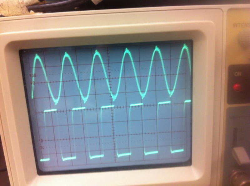
The irregularity in the sampled waveform is caused by the jitter between the trigger signal and the 48MHz clock.
Rather than using a digital delay you need to generate an analog ramp with the IDAC on board. Then use another IDAC to generate a voltage. Finally a comparator to trigger the hold of the s/h.
You should be able to do this all on the PSOC4.
Quite a fascinating idea. I didn’t appreciate that the s/h modules in such parts would work this well. Thanks.
It wasn’t only early digital scopes – The first sampling scopes were actually analog, and could capture repetitive events up to 1GHZ (in 1961). Check out the tektronix 661http://proxy.w140.com/tekwiki/wiki/661. It’s a fascinating machine (and I’m lucky enough to own a working one!)
A just recently picked up a FreeSoC2 board so I’m looking forward to checking this out. Thanks for the information.
I think some people are over thinking this (just a thought).
Any signal that is triggered buy a simple level/edge trigger is in some way periodic.
People are thinking that the output is in some way wrong and they’re right but that’s wrong.
Lets look at an old CRO (Oscilloscope) on the 20MHz scale you are seeing what is common to each scan. If there’s an error in some scans then your not going to see it unless you have 20MHz vision unlike the rest of us who can’t do better than about 20Hz vision. So you see what is common to each scan because your sight simply isn’t fast enough to see a single scan.
So yes you can use something like this to up the scan rate and make semi-periodic waves look more accurate because your eyes are not in any way accurate enough to see the error.
This still would make a very useful tool for visual output. I might give it a go with some CPLD, SRAM and a uC. If I do the SAR in CPLD then I should have a high scan rate.
> Any signal that is triggered buy a simple level/edge trigger is in some way periodic.
Yes, but only *ideally*. In practice, it has a different noise realization every time. That’s the way life works :)
There’s a hell of a lot of signal theory, and here the point is *not* looking at a real time oscilloscope but measuring and analyzing “off line” at arbitrary temporal zoom, hence your “20MHz vision” argument hardly counts.
“Yes, but only *ideally*. In practice, it has a different noise realization every time. ”
That’s a bit of a confusing way of thinking about it. If you have completely wideband noise, it doesn’t matter if you grab 0, 1, 2 or 0, 1+T, 2+2*T, etc. The signal is some function mod T, so the signal is identical every time, and white noise is completely Gaussian in amplitude, changing with every time step, so it just adds a Gaussian-distributed random number to the value each time, but it would’ve done that before anyway.
In other words, you might think “who cares about the noise? I’d get noise with my 50 MHz scope as well, and it’s random too.” The problem is that the noise isn’t wideband – it’s band-limited. And band-limiting noise means that there *are* correlations with adjacent samples, which means that sampling truly at Nyquist you will see *less* fluctuation: if the noise fluctuated way up 1 sample, it *can’t* fluctuate way down the next sample. But it completely can at 1+T samples away.
So it’s not just that the noise realization is different every time. It’s that it’s *more* different than the Nyquist sampled rate because you’ve given it a much larger bandwidth to fluctuate over.
Equivalent time sampling has been used for years and is even in some modern scopes … it works great to see waveform shapes but not for any data or anything not constant
Hi onebiozz, do you know which modern scopes use ETS? I was curious to know if/where it’s still use but the scopes I have don’t seem to use it.
A similar technique is used to get high res pictures, you make the camera vibrate and take several pictures, then you combine the many pics into a hig res one
Can someone verify the whitepaper link is working? When I try to open it I get a “not a valid pdf” error. (A mirror link for the file would be great, too.)
Was working before.
Still working for me.
The link goes to a web page that renders the pdf on the page so right click – save as won’t save the actual pdf.
Try this link for the pdf dowmload –
https://www.dropbox.com/s/ze40em4vbre0gzb/writeup.pdf?dl=1
Dear Nava, Sampling rate is not Bandwidth, two different things. Please update the post so people don’t get confused.
A few weeks ago I noticed a Cortex M4 chip, the LPC4370FET256, that claims an 80Msps 12-bit ADC. It only comes in BGA, but if you don’t want to deal with that, NXP also sells a dev board (LPC-Link2) for about $20. I assume it brings out the ADC channels to headers and with good signal integrity, since Embedded Artists sells a full digital oscilloscope implementation (LabTool) – which requires and plugs into that dev board (maybe they didn’t want to deal with BGA either).
I’m not knocking how [Carlos] did it, just saying that there appears to be a more straightforward alternative, that’s surprisingly inexpensive.
FYI: the LPC4370 is an ARM Cortex-M4 with built-in 80MHz 12-bit ADC. It’s a BGA chip, but there is a nice dev board, the LPC-Link2, for $20.
80Mhz it pretty impressive! I guess you could do some interesting SDR stuff with that too.
80 MSpS is not surprising from a 200 MHz uC.
STM32 chips (at least my STM32F407) have this feature out-of-the-box. They have 3 ADC’s which can be configured to do sampling with 1/3 clk distance. STM calls this mode interleaving or something like this.