Computer Numeric Control technology has been around for a long time. It’s at the heart of our 3D printers, laser cutters / etchers and CNC milling machines. They all work the same way — you begin with a CAD program and make some type of design. Then the computer converts the file into a set of XYZ coordinates and moves a tool head accordingly. Now let us pose to ourselves a most interesting question. What if you reversed the process? What if you could take a CNC’d object and convert it into XYZ coordinates?
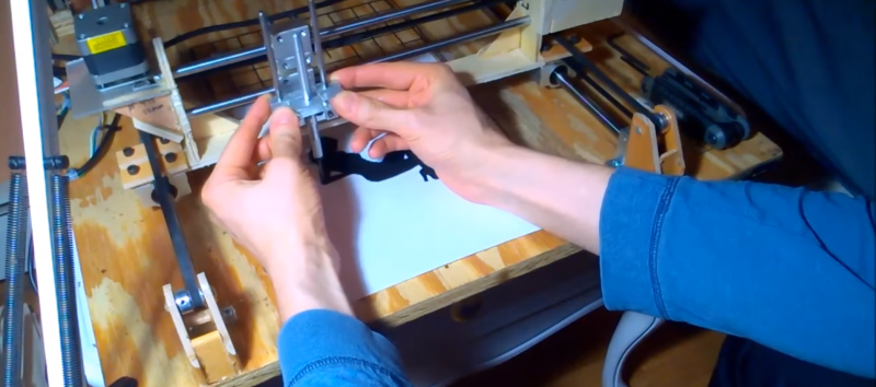
This is precisely what [dave] is attempting to do. He’s made a basic CNC outfit and installed encoders on the steppers. He then manually moves the tool head to trace out an object. At the same time, the encoders are feeding the coordinates to a computer for recording. The idea is to replay the coordinates to see if the CNC can replicate the object.
Judging from the video below, the project is a success!
[youtube https://www.youtube.com/watch?v=UZZKaExIpBk&w=560&h=315%5D


not sure what’s new or special about this just google mach 3 touch probe many many many people have made them and made the design available for all to use.
Yeah, he’s going a bit ass-backwards with it.
Scanning the piece with an optical sensor would give him more reliable points of data than driving the mechanism backwards, because he’s introducing forces that flex the machine while moving it and rattling all the backlash.
It appears that he wants to build a device similar to a copying pantograph to control another machine, so he can slap a drawing on the table and trace it without programming G-code.
If that’s the case, manual control might be the best option, especially if the slave machine is working some fussy material that needs a bit of fine touch to cut well.
pantograph raises another thought. If you wanted more accuracy than a hand trace affords you could introduce scaling. Trace a 3x picture, now hand errors are reduced to 1/3 in the final path.
That is what I was thinking. In one shop that I used to work in we’d use the probe to “copy” parts that we had to reproduce and create the toolpaths from that.
Just remember to avoid the rote reflex to turn on the spindle! The probes are expensive and a pain in the ass to rewire.
When you’re moving a CNC machine by hand, you’re doing it wrong.
In soviet Russia CNC utilizes you.
Well played, computers, well played!
Well I think he is heading in a good direction.
He chose a silhouette to enter with this method so of course we can all think of a better way to enter this data – optical scanning – image processing – and many other methods.
All the above methods take time especially if the original is not in the digital domain to start with and he made that point.
He want to be able to enter something into a CNC plasma cutter that is not already in the digital domain and this approach is fast especially given that a plasma cutter is for cutting the rough.
This could be a very effective time saving tool and that’s important in a workshop.
In my opinion, the next step should be removing the steppers and use DC motors with encoder that he already have them in the system so …
Other than that, very cool project !
This is similar to signature machines. I remember my Dad was one of the lucky ones in the 80s and 90s to have his signature recorded by a machine which would actually use a physical pen to sign his name to documents, so that it wasn’t a computer or xerox copy of his signature but an actual pen-on-paper. I never saw the machine, but I would imagine you could do something similar here.
As pointed above, this is more for artistic purposes, where you already have the idea in your mind and you don’t want to have to sit at a computer to encode it/draw it digitally. I’m guessing there’s no way to use the steppers themselves to encode, you have to have the encoders as well?
Before NC, (Numeric Control, the early systems were too primitive to be called Computers) and for some time after the introduction of CNC, hydraulic tracers were used on lathes and mills.
A probe followed a pattern, with the probe tip actuating some very touchy valves to direct the fluid flow to cylinders. The systems used a large tank and powerful pump. These tracers stored no information, the pattern was traced each time. Some tracer mills had two, three or four heads installed to speed up production.
Speed? Bridgeport’s tracer system could get up to 13 inches a minute.
Poke around the web and you may find stuff on hydraulic NC mills using hydraulic motors with chain driven screws as a step between the cylinder driven tracer mills and electric drive NC and CNC systems.
Add spirograph.
Actually, what he needs is a two-jointed arm with encoders in the joints and a stylus at the end, and some trigonometry to trace the path of the stylus and turn it into G-code.
The stylus is far lighter to move, and can be calibrated to the machine, and since it’s separate from the machine it doesn’t need to move on the same table. It can be used as a copy carver, tracing and cutting simultaneously.
looks like he started with a traditional mechanical pantograph
http://sandsprite.com/blogs/index.php?uid=13&pid=320
the idea of a stand alone electronic pantograph is interesting though.
one more thought on a standalone pantograph (essentially an accurate joystick of sorts) is that it will require more work area for now two devices. Doubling the machine as the recording device is attractive in this respect but is limited by machine size/inertia/bulk outside of the model/desktop size realm.
Uh, take a pic of your silhouette on a white background, load image in to inkscape, convert bmp to path, and use the gcode tool in inkscape? Yes, CMM is useful. This project seems like too much work to me though.