[glitch] had a cheap EPROM eraser with very few features. Actually, that might be giving it too much credit: it’s barely more than a UV light that turns on when it’s plugged in and turns off when it’s plugged out unplugged. Of course it would be nice to implement some safety features, so he decided he’d hook it up to a software-controlled power outlet.
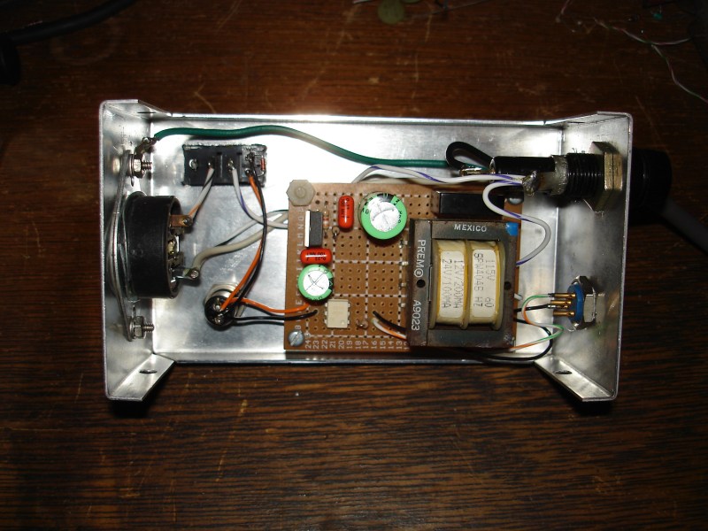
Of course, controlling a relay that’s wired to mains is old hat around here, and in fact, we’ve covered [glitch]’s optoisolated mains switch already. He’s gone a little beyond the normal mains relay project with this one, though. Rather than use a microcontroller to run the relay, [glitch] wrote a simple Ruby script on his computer to turn the EPROM eraser on for the precise amount of time that is required to erase the memory.The Ruby script drives the relay control directly over a USB to serial adapter’s RTS handshake pin.
[glitch]’s hack reminds us that if you just need a quick couple bits of slow output, a USB-serial converter might be just the ticket. You could imagine driving everything from standard lamps to your 3D printer’s bed heater (provided you use similar hardware), but it’s especially helpful for [glitch] who claims to forget to turn off the eraser when it’s done its job, which leaves a potentially dangerous UV source just lying about. It’s always a good idea to add safety features to a dangerous piece of equipment!


EPROM Timer? What’s an EPROM?
it is a electronic prom held outside Washington it is a month after nerdprom.
It’s actually the most ironic type of memory.
Erasable and Programmable while also Read Only.
However the opportunity to give the technology a better name passed long ago.
EPROMs were kind of ROMs back then because they couldn’t be erased by system they were used in. But later came EEPROMs and they weren’t ROMs at all, they are NVRAMs.
Hold on. It’s wrong. Why EEPROM should be all NVRAM?
That’s not the case. You can’t reprogram EEPROMs just like writing to RAM. The EEPROMs are erased by blocks and it’s a totally different procedure than just writing new data on a byte in ram. You have to erase the data from it and then you can write new data. So no, they are not NVRAMs.
Memory chips before EEPROM and flash. They were programmed with programmer and erased by exposing them for a few minutes to UV light. They have transparent window on them so you can see the silicon and bonding wires.
…the operative word here being ‘were’.
Look it up. if we tell you you, you wont remember it ;)
“plugged out”; grow up in a community where many spoke German, more than the did English?. I did and heard that before. As well the engine “die it”, “air forced” instead of forced air.
One of the families I’ve known says, “Shut on the light!”
No I’m a native English speaker, I’m just a bit of a language nerd too though and never miss a chance to point out how bizarre English can get.
I use to have a huge batch, just cycled them. If I can remember correctly… 3 days in directs sunlight will erase them.
Those erasers weren’t cheap. Unlike nowdays, ten bucks for nail-polish dryer and you have EPROM eraser and you can use it for exposing photo-film on PCBs.
Back in the day, I bought a 20 W germicidal lamp (fluorescent form-factor) for about $20, and a ballast for about $15, hooked them up with alligator clips, then stuck it all in a mailing tube. I didn’t use it often, so didn’t need any of this fancy-schmancy timer stuff. Don’t know how long it would take to erase one with a UV LED or four.
You can check it out right here : http://hackaday.com/2013/10/03/fail-of-the-week-eprom-reading-and-erasing/ :)
I some of his other projects that are retro-computer projects but still I wonder why still use EPROMS?
You can still get 5 Volt 256kb FLASH in dip chips so perhaps he needs the smaller sizes like to 2708 2716 etc.
I think the old chips were 24 and 28 pin. I don’t know if you can still get 5 Volts 28 pin FLASH but there is plenty of 32 pin dip still available. And because it is 5 Volt programmable you can re-flash it in situ.
I use them because I have a (mostly scavenged) stock of them, and the equipment I’m working with was designed for them. I’ve built Flash drop-in replacement modules for some of the weirder/hard-to-get ROMs (character generator ROMs, for example), but it’s quicker/cheaper just to use the “correct” ROM, especially when you scavenge them anyway!
I do use Flash and FeRAM (Ferroelectric RAM) for modern designs, of course, even if it’s for old equipment. Greatly shortens development time when you don’t have to stop and erase EPROMs once you run out!
I use them for repairing a certain vintage of music synthesisers. I keep a collection of everything from 2708 to 27512 around, and I program them using a programmer that has also been around for the last 20 years or so. Fortunately for me, the programmer software runs under WINE, or I would have to keep a Windows 98 laptop around with a serial interface to drive the programmer to program the obsolete devices.
Just to be clear, the “safety” feature is for the EPROMs, not the humans! Overexposure will destroy the EPROMs. Personally I don’t trust a quick Ruby script to protect *me* from UV exposure.
Where did you get the information that overexposure will destroy an EEPROM?
I’m pretty sue that’s not true.
First hand experience, experience of others, pretty sure it’s in a few of the datasheets. We’re talking overexposure by significantly longer than required, like forgetting the UV lamp is on and going home for the night.
Can you find a data sheet reference? I’d sure like to see that.
It’s more likely your device was damaged by something else.
I’ve used a fair number of EPROMS in the past and have left the eraser on over a two-week vacation and not had a problem.
It could also be you were using different EPROMS than aI was (I used almost 100% Fairchild parts)
I don’t have one in front of me. Wikipedia has this to say:
EPROMs had a limited but large number of erase cycles; the silicon dioxide around the gates would accumulate damage from each cycle, making the chip unreliable after several thousand cycles.
Additionally, my Intel iUP-201 EPROM programmer’s manual states that exposure times should be kept to a minimum, and longer exposure times reduce the number of erasures the EPROMs can withstand. It’s entirely likely that my failures were a result of using older parts that had already been erased a number of times. Or something. Either way, I ended up with an eraser full of useless EPROMs.
The really clever thing would not to use the PC as a fixed timer, but to repeatedly read the UVEPROM while it’s being erased and stop when it’s done.
That way you don’t over-erase it.
It’s a good idea. But you would probably want to continue for a period of time after it reads blank.
Though it’s a binary device it internally is a lot more analog. Each bit has a transistor has a metal pad fabricated under the gate. This metal pad is called the floating gate as it has no connections and is enclosed in insulation (oxide). Programming changes the charge on the floating gate and this shifts the threshold of the transistor. UV light exposure causes the charge to “bleed” away, erasing the memory. In use the transistors have a gate voltage such that the charge level determines whether they are on or off, thus reading as 1 or 0.
Transistor thresholds are temperature and voltage dependent. You could blank check at the operating voltage but you may only have bled away enough charge to barely shift the transistor from 0 back to 1 and a few degrees temperature change may shift the threshold enough for it to go back to reading as a 0. Some more time after first seeing it blank will ensure its definitely erased and firmly back to being a 1.
How long that time is depends on UV intensity and I remember the frustration of trying to rush an EPROM erase an old tube, erasing too many eeproms at once and some not being right under the tube, some EPROMs requiring longer to erase than others.
Removing the frustration of finding my last assumed blank EPROM isn’t completely erased is appealing but I’m all EEPROM and flash these days.
Yes, that’s what I was going to suggest. It’s similar to the programming protocol that some of the devices had: you were supposed to program in short pulses for each word, reading the result between each pulse. Once you got the right value back, you would do another n * 2 pulses to ensure that it was completely programmed but no over-programmed. So it would probably be about right to erase until everything reads 0xFF, then twice that much longer.
I’d humbly suggest using optoisolated triacs instead of relays. You don’t need the transformer for the coil power that way. I use MOC3020 and MOC3040 triac driver optos for a few projects of mine. One is the Toast-R-Reflow switching board. There, the MOC3020s are used to gate a pair of BTA-20 triacs for the oven elements. The other project is the J1772 Hydra, where a smaller triac is used to drive a contactor to turn the power to each car on and off (I sort of draw the line for semiconductor switching somewhere south of 30 amps. :D ), but that contactor is itself driven by a MOC3040 optoisolated driver triac.
oops. The contactor is driven by the small triac, which is driven by the MOC3040.