Adjusting the volume dial on a sound system, sensing your finger position on a touch screen, and knowing when someone’s in the car are just a few examples of where you encounter variable resistors in everyday life. The ability to change resistance means the ability to interact, and that’s why variable resistance devices are found in so many things.
The principles are the same, but there are so many ways to split a volt. Let’s take a look at what goes into rotary pots, rheostats, membrane potentiometers, resistive touchscreens, force sensitive resistors, as well as flex and stretch sensors.
Potentiometer
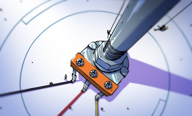
Potentiometers, or pots, are basically voltage dividers: a method of dividing a given voltage down to a lower level. As the schematic shows, a potentiometer (in grey) has three connection points. The middle connection point is adjustable (denoted by an arrow head) and makes contact with the resistance material inside at a point somewhere along the material’s length.
The voltage between the adjustable point and one of the other points (the ends of the resistance material) is determined by the resistance between those two points. If only two points are connected to then it’s considered a variable resistor or a rheostat.
In the photo is a pot with a cylindrical shaft that you turn. The plastic volume knob on your sound system is hiding one of these pots. Note the three connection points (terminals), the middle one being the one that’s connected to the adjustable point. The photo shows a new, uninstalled pot. Here’s an example of where I used a pot for volume adjustment on a peanut butter jar amplifier (incidentally this was covered on Hackaday).
How Potentiometer Resistance Changes
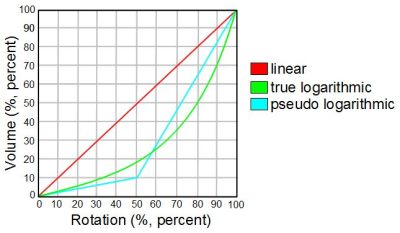
Potentiometers can have a linear range of resistances or a logarithmic range. Linear means that as you turn the shaft, the resistance values you get change linearly. Turn it a quarter of the way and the resistance will change by one-quarter the full range. Turn it half way and the resistance will change by half the full range.
But for a volume knob the volume will sound like it’s changed too fast; that’s due to the way our brain interprets what our ears hear. So for a volume knob it’s best to use a pot whose resistance changes logarithmically as you turn the knob. The graph shows how the volume changes as the knob is turned, or rotated, for both linear and logarithmic. Note that some logarithmic pots are only pseudo logarithmic and are cheaper than true logarithmic ones. These consist of two linear sections with different rates of change and meet at 50% of their rotation. Those are also shown in the graph.
This logarithmic behavior is sometimes accomplished by making the resistive element inside be tapered in shape; its width changes from one end to the other. For this reason pots are often referred to as either linear tapered pots or logarithmic tapered pots.
Another form potentiometers come in are as trimmers, or trimpots. They’re smaller than the above ones and are used on circuit boards. They’re usually adjusted just once (or very rarely) as a way to calibrate an electronic circuit.
Potentiometers aren’t all rotating components though. They can also be sliders, as shown in the photo of an equalizer on a keyboard. These are prone to dirt getting inside them and interfering with the mechanism, which is the case with the one pictured (I know because it’s mine and some are a little hard to move).
Rheostat
As I said above, when only two terminals of a potentiometer are connected to then it’s often called a rheostat. Rheostats are usually rated for a higher wattage than the types of potentiometers pictured above, and certainly for more watts than a volume control.
To handle the higher wattage they’re usually made by winding a resistance wire on an insulated core and then having a wiper slide over the wire, making light contact wherever it touches the wire. Recall the electrical symbol for a potentiometer from the beginning of the article where three terminals are used. Since you connect to only two terminals of a rheostat the symbol is different; a resistor symbol with an angled arrow (which doesn’t connect) placed through it. Below you can see both the zigzag line IEEE standard version and the rectangle IEC version here.
Membrane Potentiometer
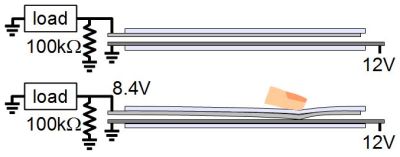
A membrane potentiometer consists of a flexible, insulating and often transparent membrane with a resistive strip attached under it. Spaced out below that is a base on top of which is printed a conductive path. When a finger or other object presses down on the flexible membrane with its resistive strip, an electrical connection is made to the conductive path. This results in a voltage at the terminal of the resistive strip. The voltage varies depending on where the connection is made with the conductive path. Note that this is the same circuit as in the first schematic for a potentiometer at the beginning of this article.
The resistance for one from Sparkfun called the SoftPot varies linearly from 100 ohms to 10 kilohms with a 1 watt rating.
If the connection isn’t always present, as when a finger is used to make the connection, then a pull-down resistor should be present (e.g. 100 kilohms). However, with some membrane potentiometers a magnet or a wiper is always putting pressure on the membrane, resulting in a constant connection.
Resistive Touchscreen
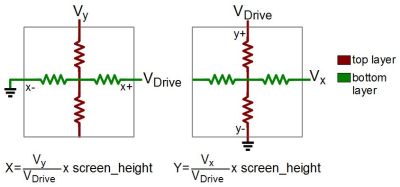
A resistive touchscreen is similar to a membrane potentiometer except that both layers have resistive material on them and that material is transparent. The front membrane is flexible and also transparent so that a finger or stylus can press against it to create a connection. Think about inexpensive PDAs from a decade ago, or some children’s toys still today. The technology is still in use but the smartphone revolution has been built on capacitive touchscreens which don’t require a flexible membrane.
For a 4-wire resistive touchscreen, voltage is first applied across the top layer while a value is read from the bottom layer in order to get the X value. Then voltage is applied across the bottom layer while a value is read from the top layer to get the Y value. All this is done in milliseconds and the screen is constantly being scanned for these values.
The calculations are all done by a supporting controller. Resistive touchscreens are not as responsive as capacitive touchscreens and often require a stylus to get the required accuracy. They are used in lower end smartphones.
Force Sensing Resistor
Flex And Stretch Sensors
A flex sensor is a resistive material, carbon for example, coated on a flexible membrane. When the sensor is bent this causes the material to stretch, increasing its resistance in a manner correlated to the bend radius. From one datasheet the resistance when flat is 10 kilohms but could be twice that when bent 180 degrees with the two ends pinched together. A popular example of its use is in the fingers of gaming gloves like the original Nintendo Power Glove (here’s one hacked to control a quadcopter). Bending a finger registers as a change in resistance giving an indication of how much the finger is bent.
A stretch sensor works on the same principle except that you stretch it to increase the resistance. And example is a rubber cord that’s infused with carbon-black, looking much like a bungee cord. Taking one example from Adafruit if you have a 6″ length that’s 2.1 kilohms and stretch it to 10″ long then the resistance increases to 3.5 kilohms. Another example is a conductive yarn made up of steel fibers mixed with polyester and there are others that are in the shape of ribbons or belts.
Resistance Now Minimized
That is a great collection of the manually variable resistors you’ll find in use these days. We may have missed one or two and if so let us and everyone else know in the comments below.
If you want to learn about resistors whose values don’t change check out my previous article on fixed value resistors (well, they do change slightly due to temperature, humidity and other factors be we talk about that too). I have one more article in this series planned: resistors whose values change without human interaction (e.g. a photoresistor’s resistance varies with light). Be on the look out for the final installment.



I like the article with one small correction – the pull-up resistor you mentioned in last paragraph of membrane potentiometer should be pull-down, as indicated in schematics, perhaps.
Good catch. Fixed. Thanks!
Another one:
” Let’s take a look at what goes into rotary pots, reostats, membrane potentiometers, resistive touchscreens, force sensitive resistors, as well as flex and stretch sensors.”
Misspelled rheostats.
That’s the problem with spell checkers that don’t know how to spell a word, you just ignore the underlined word. We need spell checkers that know when you’ve misspelled a word that they don’t know. :) Fixed. (Actually I take extra care in that case — missed it this time somehow.)
Right, techical terms you just tend to assume they don’t know them.
And another: “In the photo is a pot with a cylindrical shaft that you turn. The plastic volume _know_ on your sound system is hiding one of these pots”
pretty sure that should be “knob”
I was trying not to nit-pick, but I can’t fight this feeling anymore that something needs said.
but that’s ok, Hack-a-Day, I’m gonna keep on loving you.
:D ♫
*hums quietly*
Most “log” potentiometers are not very “log” and it would be better to use a linear potentiometer with a resistor to alter the curve.
http://sound.whsites.net/pots.htm#taper
http://sound.whsites.net/project01.htm
“Unless you pay serious money, the standard “log” pot you buy from electronics shops is not log at all, but is comprised of two linear sections, each with a different resistance gradient. The theory is that between the two they will make a curve which is “close enough” to log (or audio) taper. As many will have found out, this is rarely the case, and a pronounced ‘discontinuity’ is often apparent as the control is rotated.”
The article we are replying to mentions this.
“Note that some logarithmic pots are only pseudo logarithmic and are cheaper than true logarithmic ones. These consist of two linear sections with different rates of change and meet at 50% of their rotation. Those are also shown in the graph.” (see the adjacent graph)
In electronics, close is often good enough. That’s why you can buy components with varying degrees of tolerance. need 1 ohm? well, 0.877 is often close enough, etc.
Not everything needs 0.1% precision, nor deserves the money that comes with that kind of accuracy.
Doing instrumentation design? sure, go ahead and spend the money.
Doing a blinky light and need a current limiting resistor for your LED? You don’t need anything fancy.
” Resistive touchscreens are not as responsive as capacitive touchscreens and often require a stylus to get the required accuracy.”
I miss resistive touch screens. True, they weren’t as responsive but as often as my capacitive touch screen phone reacts to me just picking it up in ways that I don’t want it to register as a touch, being less responsive is just fine by me. My old Zaurus and later WinCE phone both responded just fine to a fingernail provided I didn’t cut it down all the way to the quick. I didn’t have anywhere near the trouble with accidental clicks as I do now.
As for the ‘accuracy’ comment. I don’t know where you are coming from. Resistive touch screens were way more accurate than the best capactive touch screens today. That’s what I really miss. With a fingernail you could press any button. With a stylus you could draw a picture! You could even write text which could then be ran through an OCR as an alternative input method!
Today’s capacitive touch screens really suck for accuracy. Or maybe it’s resolution. Thats why you can’t use those old pointy stylus with a capacitive touch screen. It won’t even register. Instead you have to use those big rounded ones. Drawing or writing anything on a phone sized capacitive screen is like trying to sign a receipt with a giant chunk of sidewalk chalk. A simple stick figure is about the best you can hope for. Yuck!
The real reason everything is capactive now is multi-touch. You can’t get that with a resistive screen. Personally, I like multi-touch but I would give it up in a heartbeat to get the resolution and accidental touch-rejection of a good resistive touch screen.
A better sollution would be to combine the two. So long as only one touch is registering take the data from the resistive layer. If multiple touches are registering take it from the capacitive layer. That would at least restore the ability to draw a picture or recognize handwriting. Unfortunately there is a company, I forget their name but they patented this. I don’t see any such devices out there so I guess they are just another patent troll holding us back from having nice things. I so hate this system.
What I don’t like about capacitive is that you frequently have to be in solid contact with device for touch to register. Your phone is sitting on the table, or your tablet on a stand and it won’t swipe, scroll or click a radio until you grab it with your other hand.
Also phone sometimes doesn’t like being held by just the edges, have to pull it back into my palm to get it to register reliably. Trying to use one handed is unreliable because of that too.
I actually detest touch screens in anything bigger than about 8″, because more than that and your fat hand has to be in the way, blocking out most of your screen real estate, it’s just about acceptable when you can get away with a single finger. With a larger screen you end up hand hovering, may as well be using a 7″ tablet vertical with your thumbs as use a 10″ or larger tablet with stuff you need to interact with on the left side, because that’s all the screen that’s actually visible most of the time anyway.
“What I don’t like about capacitive is that you frequently have to be in solid contact with device for touch to register”
Unlike resistive touch screen? You think you can control those from a distance? It’s quite the opposite.
What I mean is some other part of body other thsn the finger you are using has to have firm contact. Thought that was clear given examples of trying to use on in stand or lying on table. I also have resistive devices that do not have these issues.
To me it sounds like you just have a crappy phone and are drawing wide conclusions from that.
No have had issue with multiple devices. Some days i have trouble with multiple devices, other days they work okayish.
Maybe you just have a crappy charger. Does the same happen if it’s not connected to anything?
I’m mostly suspicious of days when the air and my skin is super dry, say below 35 percent humidity. Today is damp, everything registering perfectly.
Some Samsung devices have a nice, precise stylus. So do the latest iPads, although they’re not particularly friendly to those who like to hack their devices.
Yeah, my S5 is great even without a stylus. It even has a ‘glove mode’ that detects finger from about .3CM away. :)
nice art joe!
I know that this article is about Variable resistors, but I once made a Variable power supply (in the 1980’s) that used a Variable transformer.
I haven’t seen any Variable transformers for sale for years now.
I guess it’s cheaper to manufacture IC’s that can change the voltage.
Oh. And Baldwin’s variable resistance “contacts” to make attack not just click on like a Hammond. One can play each note carefully swelling each note, which no modern midi keyboard will do.
A lot of displays in medical equipment are resistive. It alows use while wearing gloves.
Often need re calibration and lack precision.
My kids found a natural variable resistor in the garden the other day, they are always digging stuff up then wanting to identify it and test it’s properties. It was a lump of high grade coal from the edge of a band of coal so it had fine layers of clay and carbon in it, one of the edges was diagonal through the layers so that if you put a multi-meter probe on the top and moved the other down the edge the current had to travel through increasing numbers of clay layers, whereas just changing the probe distance across the top layer only altered the resistance a small amount proportional to the conductivity of just the carbon. How do we know it was coal? With a sunlight and lens test to burn a small spot and smell the coal tar that evaporated off.
What, no borg jokes? ;)
Nice article though, really interesting, I know a little more now.
It would seem that this time, resistance was not futile.
The circuit of the “sound source”, “log pot” and “amp” is a problematic way to control volume.
Pot’s often have issues with dust and need to be oiled occasionally. The dust causes the wiper to go open circuit as the pot is rotated.
The ratio between the pots total resistance and open circuit is infinity so you end up with a very loud clicking or scratching sound.
Instead you can wire the center of the pot to one side so that in the open circuit condition the resistance is limited to the total resistance of the pot. The ratio is then far lower and the effect of dust is far less concerning.
A second external fixed resistor can be used as the second part of a divider. This can be used in the negative feedback path of the amp.
Or get into the modern times and use a digital potentiometer or PGA to do the volume control.
“A dimmer switch for a light is a rheostat.” I had thought that, at least in the days of incandescent lamps, they operated rather by pulse-width modulation: when the dimmer was set to 50% intensity, the light was on 50% of the time and off 50%, whereas for 10% intensity there was a full-voltage pulse for 10% of the time followed by nothing for the other 90%. The pulses were fast enough that the filament didn’t have time to go out. This doesn’t waste energy as a rheostat does.
(I checked this with Big Clive, so it must be true ;-D https://www.youtube.com/user/bigclivedotcom/ )
Right, in common parlance a light dimmer might be called a rheostat, but I haven’t actually seen a real rheostat in that use for household lights since the last century, and that was probably a 20 year old install. They remained more common for automotive interior and dashboard lights.
I think we had a TRIAC light dimmer already in the early 1970s. I remember my parents calling it expensive :-)
Well compared to a candle it *was* expensive.
The leftmost photo I show in the Rheostat section is of a dimmer switch taken from my storage shelf. I can’t say exactly when but I bought it at Home Depot sometime probably 5 to 10 years ago. It was for mounting in the wall for dimming the lights. But I wouldn’t doubt that newer ones use PWM. I’ll have a look the next time I at a hardware store.
You would have had to buy it about 60 years ago for it to be an actual rheostat. Phase control with Triacs are how light dimmers have worked for that long.
Dimmers for lights have not been simple rheostats for a very long time. In your picture, the black thing on the right riveted to the aluminum face is a Triac. It is using phase control to switch on at later times in the AC waveform, a form of duty cycle PWM.
Ultrasimple version, usually there is also an inductor in series and a few extra capacitors and resistors to control switching transients:
http://amplifierlab.com/wp-content/uploads/2010/05/Simple-Lamp-DImmer-Circuit.JPG
Insert now overly cliched thumb up icon.
Followed by test post – please ignore.
Yup, that schematic’s pretty close to what I’ve got, just with the added inductor, resistor and capacitor you mentioned. The black thing riveted to the aluminum face is labeled 130-174, and though I couldn’t find a datasheet I found this https://www.aliexpress.com/item/Scr-thyristor-130-174/1228003836.html. I’ve removed the mention of the dimmer from the post. Thanks guys!
High power wirewound potentiometers, aka rheostats, are often used as local volume controls in PA speakers.
Although I’ve seen some more expensive systems that use what looks like a wirewound rheostat that is actually a small audio variable autotransformer.
I’m continuously reading about variable resistors but to be honest not all the articles are helpful in terms of content they shared. I’m a newbie so searching for something where I can easily understand. For example this one I just read https://www.derf.com/how-a-variable-resistor-works/ this is good but information given here was not too much elaborated. Thanks for sharing helpful content.