We love squeezing every last bit of silicon goodness out of a tiny chip, or at least we delight in seeing it done. Today’s analog/digital hack is one of the sweetest we’ve seen in a while. And it’s also a little bit of a puzzle, so don’t scroll down to the answer until you’ve given the schematic a good think-over.
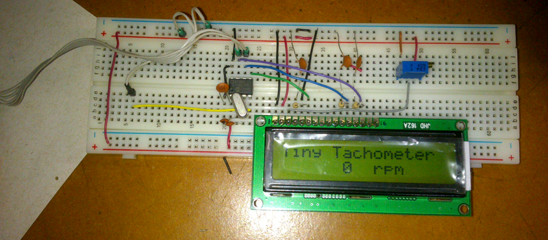
[Claudio Larios] built a tachometer with LCD display, using only an eight pin PIC microcontroller for brains. (Translatrix.) Two pins are taken up by the power supply and one reads a Hall sensor, leaving only three pins to drive an LCD display which needs six signals. The problem to be solved is the fundamental mathematical issue that three is less than six. Now have a look at the schematic.
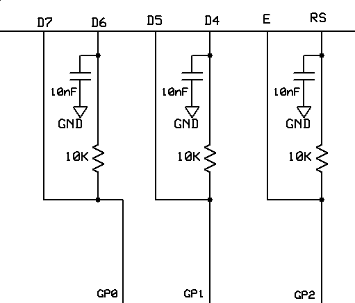 If you’ve not played with the Hitachi HD44780 LCD controller before, it has four-bit and eight-bit data modes. In four-bit, used here, you only need to send data on D4, D5, D6, and D7. RS selects between command and data mode, and E is the clock signal that latches the data in on a falling edge. Mull that over a bit before reading the next paragraph.
SPOILERS!
What [Claudio] is doing is essentially using the 10 nF capacitors as little memories! (Look into DRAM if this analogy seems a stretch to you.)
In a first pass, the PIC’s pins are set high or low for a longish period of time (500 microseconds), long enough to charge or discharge the capacitors through the 10K resistors. In a second pass, the values for D5 and D7 are set, and the E line is strobed up and down almost immediately to latch in the values on the no-capacitor lines.
The second pass happens so quickly that the capacitors can’t charge or discharge fully and RS, D4, and D6 read in whatever logic value was set during the first pass. Brilliant! (Oh yeah, this project was about a tachometer. We got distracted by the shiny pin-stretching tricks. We’re sure it’s a fine tachometer.) Did you see how he pulled that off with only three pins?! And no shift register?!?
HaD reader [danjovic] sent us the tip and did a little work on the code, verified that the technique worked, and provided the banner photos of his recreation. Many, many thanks!


you know I really hate to be critical and this is a neat trick but a 16pin part isn’t going to cost any more than an 8 pin.
Space saving? Other pins already used? It’s a trick worth remembering for that time you might need it.
Or remember to use a display with an I2C translator on it and use even less pins.
There’s always one.
What happens if your touchscreen is slightly off or forgets calibration when ordering the 16 pin one and it clicks order for the eight pin package?
Or you type your keyboard faster than you can think and press tab and enter a few too many times?
Might as well make the most of what you got I’d say.
On the other side:
– If you got 10 8-pin micros and 2 16-pin micros at hand and the brainpower to pull things like this off, there’s nothing stopping you.
– Availability – our local shop has plenty of ATtiny85 but no 84, and wherever the 84 can be bought, the price is unreasonable.
– All those ATTiny85 development boards with bitbanging USB are hella cheap.
– If you’re trying to shave off as much of your BOM as possible, you might want this trick and a couple more.
I’d just put a shift register though, but I can imagine not having one at hand and it’s likely to happen in certain circumstances.
space saving and part counts I don’t think so, r/c is two extra parts per pin and you have to tie them to a supply.
‘local shop’ I can’t imagine being able to go to a local shop and buy components. must be great!
Well, 6 extra parts per pin vs shift register. Depends on what’s cheaper to add to the board – there might be the case of already having same caps and resistors on the board, so it won’t cost more in terms of assembly =) It’s not such a big deal, of course, just a case that’s rare enough to appear.
Yeah, then there’s also lack of shops in certain areas, or weekends/holidays when you just want to finish that damn project and every bit of ingenuity counts.
Also, the board layout and code seems simpler compared to the shift register approach. That’s an advantage in my book =)
this is why I am my own local shop. IC’s are cheap and storage is easy so I buy gobs of common chips every time I have a little extra cash. Ali Express and Jameco are your friends….
>commenters complain when something is not a hack
>commenters complain when something IS TOTALLY A HACK
the only winning move is not to scroll down to comments
Best comment by far.
No, the winning move is to know which comments to not take seriously.
The winning move is to take the comments as humor. Everyone knows that humor and laughter have to do with an interrupted defence mechanism. So humor keeps your emotions in check. And you learn the most when your emotions are calm.
See how the comments actually make you smarter?
live by the bantz, die by the bantz
No, the winning move is to know which commentERs to not take seriously.
B^)
You made my morning… well done.
+1
If there’s absolutely no thing to complain about, there’s no point in commenting in the first place. The very definition of inane is an online comment board full of “Kudos!” or “Awesome you rock!”. If it’s really that good, give the guy a dollar or something.
A cat lives on praise, a dog by pats on the head.
-old proverb
Dax says, as he complains about people complaining that people are complaining.
Naturally. If there’s nothing to say, then don’t say it. If there is, then say.
Should one a man of wisdom meet
who points out faults and gives reproof,
who lays a hidden treasure bare,
with such a sage should one consort.
Consorting so is one enriched
and never in decline.
Let him exhort, let him instruct,
and check one from abasement.
Dear indeed is he to the true,
not dear is he to the false.
-Dhammapada
Now THAT is funny! Well done, Brian. ????
I guess I need to give you a dollar now.
Kudos!
Wrong!
I vote Comment of the year!
And how do you proceed if you are in the middle of the Sahara desert at an 8 million dollars oil drilling rig which is about to explode, and you have only five minutes and an 8-pin microcontroller available to build the safety controller which should trigger the hole seal procedure? You tell the supervisors and the investors you have to buy a 16-pin part? Or you carry on with whatever you have available, fix the damn thing, save the day and get your pockets filled with $$$?
Congratulations for this hack.
This is brilliant.
Do you have a mullet and had a TV series once…?
Nope… even in my dreams I did not ran a TV show. You don’t have time to do such things if you live in Eastern Europe. But I’ve been in that scorching hot place as a maintenance/automation engineer. It was the closest place from Hell where human hearts were still beating. And I’ve been through all sorts of weird situations where experience – and most important https://hackaday.com/blog – were extremely helpful.
he is comparing you to macgyver, which I think was recently rebooted.
haven’t watched the show. not sure if it is any good.
Maybe, like me, he doesnt have the money to go buy a new part and has to work with what he can find cheap/free?
Things are changing for me and I can now start buying parts, but when I have needed a part, and couldnt buy it I had to go find it, or find something that I could “bend” to do the job. You can be critical sure, but in this case it just comes off as smug. Remember some of us lack the financial resources that so many people take for granted.
woah lots of angry people here huh? I never said he was a dickhead for doing it or anything, i’m not trying to have a go.
david I’m in your boat, I can’t afford to buy a handful of neopixel rings and keep them in my junkbox just because they look cool.
all I’m trying to do is let people know that just because the 8 pin is half the size doesn’t mean its half the price, and even though these r/c parts cost fractions of pennies it adds to the cost and complexity.
doing something interesting like this is great and you should relish the opportunity if it presents itself. I’m not saying its not.
Yes, these “hacks” don’t belong here on “procurementengineer.com”.
I once had a 40 pin part, and used all of them. One more pin available is a huge deal when you are using the whole part.
very elegant. serial/parallel at the same time
8-3=3 ?
It was about the signal pins, the power supply pins are excluded. But yes, you are right. It would be 5 in total, with the PS pins.
He’s probably not using the programming data and clock pins. It would definitely save development time. Also I seem to remember on the 8-pin PICs that there is usually one that’ll only do input.
External crystal
could you go a stage furrther and use 100uF capacitoirs with 1Mohm resistors in conjunction with the above, and turn the three pins into 9 ?
You could use a multitude of time constants, I’d probably plump for 20x the previous for each stage.
Okay, Who’s it going to be that gets this down to a single pin using only jellybean parts?
Two is a minimum because you need one trigger pulse that won’t interfere with the data lines.
I was wondering the same thing, but at what point do all the additional components required to hack the system exceed just plopping down a shift register?
I actually do like this hack. Not only is it a fun thing to just play with, but you can argue that you can reduce your BOM cost in this instance. But that only goes so far before you’re actually costing more to hack it :)
Problems with stability.
It’s a tachometer–not mission critical, at least in your vehicle. You have your ears for backup.
It’s only a small text display. If it does go wrong, you get a bad character, til the next time it’s refreshed, not life or death. As long as he uses a long enough charge / discharge time, and the LCD is quick to sample the pins, should work fine. It’s a smart idea!
Maybe, maybe not. In the code as written a long period is 500x longer than a short. There’s a really big difference between the two, cap-voltage-wise.
I did the same thing some years ago with shift registers when I was learning electronics.
Never did anything with it, though. Just flashed some leds to see if it worked.
You : “same thing […] with shift registers”
The article : “And no shift register?!?”
Is it really the “same thing” ?
I mean like the one Stajp posted below. I was using a 74HC164, so it was just the clock and data, no latch.
Also, I wasn’t controlling a LCD, just a bunch of leds.
“Once I… no, that was someone else.”
-Steven Wright
Not bad.
Don’t forget to disable interrupts during the procedure, to preserve proper timing
Always fun to see methods reinvented. I did this 30+ yrs ago to get an extra control line. And the same concept in this EDN Design Idea:
http://www.edn.com/design/systems-design/4427215/One-wire-brings-power—data-to-LCD-module
nciswatch,
I thought of this EDN article too, but we should give the author his due.
While he may be using the same technique as described in that EDN article to strobe the E & RS lines using only one output pin, the technique he describes to setup D4-D7 using only two output pins is not the same as that EDN artlcle,
I’ve read a dozen or so posts about how to drive LCDs and this technique is something I have not seen described anywhere else. Kudos to the author for coming up with this clever hack.
Add aging and temperature, and this neat trick goes kaboom.
Circuits like these tend to fail when you need them the most, and expect it the least.
There’s a reason why we ditched RC circuits and now use counters everywhere.
Ok, I may be a little bit biased, because I have to design electronics that works from -40 to +125°C, over 20 years.
However, aging and temperature variation is solvable too. If you can switch the output back to an input you can calibrate the charge/discharge characteristics occasionally. That would also be advisable with [meme]’s suggestion of multi level, but then you’d probably need an ADC input.
As long as the time constant is many times longer than required, variations in the R and C shouldn’t keep it from working. Most circuits don’t have the luxury of being able to build in a 100x safety margin.
Yup. It’s a bizarre capacitor or resistor that goes off by a factor of 10 with age or temperature. You can build in as much margin as you want in the software. Since it’s just sending a few bytes to the LCD, there’s no great hurry. Seems pretty foolproof to me. Eventually the heat death of the Universe will stop all circuits working, but til then there’s plenty of decades old circuits still doing their job, solid disc capacitors and ordinary resistors don’t change that much. If ancient TVs can still work, this simple little hack will.
So, develop yourself a LCD that works at 125.C . It’s not a new standard, just an approach that might comes in hand sometimes (i.e.DIY projects). Don’t worry, NASA is not going to use this!
So he’s doing
http://www.romanblack.com/shift1.htm
but using more pins? :D
Hmmm, looks a lot like how WS2812 / NeoPixel LEDs communicate!
Yep! Good find.
I wonder if that’s how 1-wire actually works on the inside of the chip.
To be honest, I have Roman Blacks site bookmarked for years, as it has some neat tricks. I saw that Shift1 system a long time ago AND I use 1-wire devices regularly, and I never made the connection. But it really looks very similar. Thanks for the observation!
Or you could use an I2C type LCD display, which are cheap and freely available from your web supplier of choice. Requirement: two pins.
Or you could buy a mechanical tachometer. Requirement: zero pins.
Wonder if this could be used to run a clock along side data over a single wire into a shift register?
Sounds like another back of the drawer experiment waiting to happen…
I’m thinking along the lines of a single parity/enable (logic high) bit tacked on the end of the (byte long) packet so when the buffer is full the parity/enable bit triggers a send-parallel and clear by switching such circuits on. Could be an 8th bit or 9th bit (byte+logic high).
I did something along those lines in college. I used two 5 bit shift registers, and the first bit shifted in must always be a 1, the second bit is the command/data line, and the rest are the 8 parallel pins. the leading 1 bit would trigger an RC circuit at the end of the chain that would trigger the LCD to read the 9 input pins, and then clear the shift registers.
Nifty little trick. That clickbait title though…
Shift register vendors hate this trick!
You won’t believe this pin-saving technique!
This pin-saving trick will change your life.
Find how to save pins with this little trick !
Electronics companies hate this little pin saving trick!
You’ll be amazed how she looks after shaving off 3 pins with this secret!
Is this title not 100% factual? The only real clickbait here is the exclamation point. Would you really prefer “RC Time Constants Reduce Pin Count On LCD Screen Circuit”?
I honestly skipped reading the article and went directly to complain in the comments (click on coment link from the blog). In this day and age of fake news and ads disguised as news one can’t afford to click a baited headline.
I agree. Can’t stand watching all that trash on CNN in this day and age.
Title was mildly clickbaity, but it’s Hackaday… I know they’ll at least have content on the other side of the link.
Actually yes, because my brain automatically disregards clickbait-style titles as trash, which gets subconsciously ignored.
Always err to the safe side when it’s a choice between ‘attention grabbing’ and ‘actually factual’ in these modern tabloid times.
I actually only reluctantly clicked the “comments” link due to the amount of comments displayed, just to see how people would tear the title to shreds.
Clever trick! I can’t get these envy guys trying to find drawbacks, I guess they do this to justify the fact they didn’t have the same idea before. When you have your own clever idea you won’t need to act like this. Einstein is criticized until nowadays for some envy smartasses that are unable to do any better. Shame on you…
this could be used to convert morse code into binary….
Kind of an analog shift register.
Th author of the article hasn’t been taught Obama-core math though or they would know this is clearly wrong: “The problem to be solved is the fundamental mathematical issue that three is less than six.”
I’m having to hire a math tutor for me daughter because I can’t figure out why 3 is no longer less than 6 either.
Be something if one could use board capacitance to pull off something like this.
https://www.youtube.com/watch?v=028J8oUn71E
This is HaD! Someone has to say that you could repurpose / upcycle a digital alarm clock for this instead of bothering with RC time constants.
Brilliant !
but no t for me, i use 3 wire SPI OLED display these days
Amazing. No, realy, A!MAZ!ING!
That’s ingenious!! I have myself used the same trick before to gain one pin but as many others here I have then stopped after that and never thought about pushing this idea farther. That’s why I got amazed and shocked at the first sight of this circuit and I couldn’t help but assembling this circuit to see it working and probe it with my own scope!
I read a comment here complaining about the two extra parts per pin.
Considering that the addition of an RC filter per every pin is necessary for an EMI robust design in any case, this is no extra parts count at all.
You could argue about the minimum necessary signal riste time in case the display has a CMOS input stage without Schmitt-Trigger inputs.
Hacks like this one are not about parts, pennies, or place. It’s about your brain.
That puts it perfectly. Thanks!
analog memory, let me see
1) can be made at home without needing any memory chip to speak of…
2) works for situations like this and solves a problem
3) allows you to hack a board that does not have room for a shifter
4) pisses off everyone that thinks this is an unacceptable use of spare time because you could just buy a bag of 1000 shifter ICs for pennies each, yeh, and i could also buy a bag of… but not everyone buys stuff online or lives in shenzen or near an abandoned electronics lab from the 80’s
it’s a win in my book!
and the comment of being able to add-in 100x margin of error is spot-on, there’s no way a 10nF cap will be down to less then 1nF in less then 50 years unless the board has water-damage, in which case ALL components will degrade much faster.
and even then, the code can always be adjusted to use 500x margin and you still will not notice any speed hit; unless your using a “substance” (or a mix) to temporarily slightly enhance your retinal update speed. this may cause counter after-effects and addiction.
Slick.
I looked for the term multiplexing in these comments but didn’t find it used anywhere. This RC time constant multiplexing scheme is a brilliant hack IMHO. Intel used multiplexing on the 1101 DRAM chip for the address lines because of similar pin constraints but used the full voltage swing to the ground and positive rails. In fact an excessive RC time delay was/would have been disastrous in that environment. This trick however, requires, that digital intelligence exists on both ends of the bus for the clocking in of the multiplexed data information delayed by the RC time constant and that makes it a great idea. Music has been sent serially over a single line and reassembled at the point of use especially in commercial airplanes to also save weight in the fuselage and I’m sure there are many other applications for saving pins that would be achieved by using this trick. But the RC time constant would only be effective when the bus length is short enough so that the wires don’t introduce enough of its own resistance and capacitance to affect the engineered RC time constant…