Building a software defined radio (SDR) involves many trades offs. But one of the most fundamental is should you use an FPGA or a CPU to do the processing. Of course, if you are piping data to a PC, the answer is probably a CPU. But if you are doing the whole system, it is a vexing choice. The FPGA can handle lots of data all at one time but is somewhat more difficult to develop and modify. CPUs using software are flexible–especially for coding user interfaces, networking connections, and the like) but don’t always have enough horsepower to cope with signal processing tasks (and, yes, it depends on the CPU).
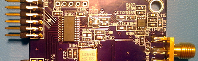
[Eric Brombaugh] sidestepped that trade off. He used a board with both an ARM processor and an ICE FPGA at the heart of his SDR design. He uses three custom boards: one is the CPU/FPGA board, another is a 10-bit converter that can sample at 40 MSPS (sufficient to decode to 20 MHz), and an I2S DAC to produce audio. Each board has its own page linked from the main project.
You can find the C and Verilog sources for the device on GitHub. [Eric] also has a great block diagram and description of how everything works available. So far, the device can handle AM, synchronous AM, narrow-band FM, as well as upper and lower sideband (or both at once). It can also send raw IQ signals directly out for further processing.
Oddly enough, we haven’t talked about [Eric’s] design before, but a picture of it appeared in a past post about (among other things) the PMOD connector system (since the DAC uses PMOD as its interface). [Eric’s] device handles about 20 kHz of bandwidth at a time. If you want something more (also with an FPGA), check out FreeSRP.


DSPs are still a thing.
I think DSPs are becoming less common because ARM Cortex M4’s include the DSP instruction set and a hardware FPU.
http://www.st.com/en/microcontrollers/stm32f303.html?querycriteria=productId=LN1531
More to the point, DSP focused architectures are becoming less common because general purpose microcontroller architectures are growing DSP-like functions.
Nice work.
Some constructive advise: You could improve your front-end immensely by doing a better job at an anti-alias filter in front of the ADC. 50-ohm followed by 20pF is not good enough (only about 250MHz 3dB cutoff with) Nyquist low pass should be steep filter attenuating all frequencies above 10 Mhz for 20 MHz sampling rate (unless you are doing band-pass + under sampling) . You probably also want to design the filter to be linear phase. .. especially with 20 MHz bandwidth.
The RXADC board was designed to be as broadband as possible in order to allow experimenting with IF undersampling. I have a selection of filters that I insert prior to the driver amp to support different bandwidths which are described on a separate page at my site: http://ebrombaugh.studionebula.com/radio/filter5/index.html
If I were trying to process the entire 20MHz of available bandwidth then linear phase might be helpful, but since the iceRadio design downconverts and decimates to a fairly narrow bandwidth that’s not so important in this case.
Sorry, I missed the part about where you had several external filters. Just trying to help. Nice project. I’ll check it out more closely this evening.
>40 MSPS (sufficient to decode to 20 MHz)
Naw, you don’t say?
Sometimes I really wish this site were more pretentious.
Sometimes I really wish the comments on this site were less pretentious.
Sometimes I really wish the responses on this site were less pretentious.
Sometimes I wish the pretentiousness on this site was more responsive.
+1
That goes to show that you, dear anonymous, have very superficial knowledge.
a) 40MS/s inside an SDR receiver doesn’t tell us whether he’s doing bandpass or complex baseband sampling. With that number, we know he’s doing real-valued sampling
b) just because your ADC covers a bandwidth of x Hz doesn’t meant that the signal fed to that is also that close to that bandwidth – for example, you could have a filter that is 16 MHz wide and has a 4 MHz wide transition between pass- and stop band, and these 4 MHz would then overlay with the aliases “from the other end” in the upper and lower 2 MHz. So this is the author inherently claiming he has a system with a nearly perfect filter (which he hasn’t).
If that’s the case then the article is poorly worded in that regard.
Following a term with brackets is akin to i.e. and should state the *same fact* in other words.
My discussion of the front end processing on this project is deliberately ambiguous because I have used several different types. For the simplest case I have a 5th-order LC low pass filter with ~20MHz corner frequency which won’t prevent aliasing up in the 15-20MHz range but is fine for most SW and amateur bands below 20m. I also have a number of different VHF downconverter designs that I’ve tried, some of which use IF frequencies above 20MHz and require bandpass undersampling.
The main thing to take away from this is that up to 20MHz bandwidth is possible under ideal (and mostly unrealistic) conditions but I’m not claiming to have actually achieved that with the hardware on my bench.
I don’t think it is pretensions at all. [Al Williams] has demonstrated a skill set that suggests that he clearly understands Nyquist frequency. Perhaps you meant condescending or demeaning, in which case I would still disagree because there is a broad readership here and there would be those who have not previously come across Nyquist frequency.
It’s always better to provide more information than insufficient information.
Also worth noting that HaD has previously written up the ARM + FPGA board that’s used in this rig:
http://hackaday.com/2016/07/11/stm32-and-fpgas-in-a-tiny-package/
Will be able to decode DAB+ ?
DAB+ is not really what this is designed for. This is mainly an HF narrowband receiver, mainly focused on analog modulations. DAB+ is a compressed digital waveform broadcast in the 88-108 VHF FM band.
DAB+ is not in the FM band at all, the US HD-Radio system uses the FM band.
DAB has 4 modes of operation in 4 different frequency bands but predominately when most people refer to DAB/DAB+ they mean 174–240 MHz.
https://en.wikipedia.org/wiki/Digital_audio_broadcasting#Bands_and_modes
https://en.wikipedia.org/wiki/Band_III#Radio
I stand corrected. Errors in frequency range aside, this board is not intended for those types of signals.
If you really want to listen to DAB/DAB+, spend $10 on a RTL-SDR dongle and use this software (player + drivers [Treiber])
http://www.ukwtv.de/cms/downloads-aside/281-dab-player-von-andreas-gsinn.html
(use Google translate if you can not read German, the software itself supports the German, English, French, Italian, Dutch and Polish languages).
I have a RTL-SDR, but application on your link is only for Windows. Is there a so easy solution for Linux ?
ebrombaugh: The Blinkenlights Trolls are out in full force on this thread. Awesome job! The fact you could squeeze that much into a Ice5LP4K is a borderline miracle.
Thanks! I did some more tweaking on the design and boosted it up to 14-bit 50MSPS for the ADC input and it works pretty well. I’ve still got some more things I want to try with it, but these FPGAs are pretty capable if you just manage the resources carefully.