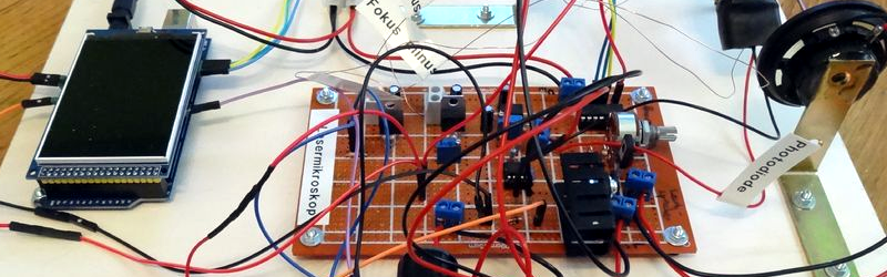
We’ve seen a lot of interest in LSM (LASER Scanning Microscopes) lately. [Stoppi71] uses an Arduino, a CD drive, and–of all things–two speakers in his build. The speakers are used to move the sample by very small amounts.
The speakers create motion in the X and Y axis depending on the voltage fed to them via a digital analog converter. [Stoppi71] claims this technique can produce motion in the micron range. His results seem to prove that out. You can see a video about the device, below.
Oddly enough, [Stoppi71] found that older CD drives were easier to work with because they were not as miniaturized as more modern versions. The device uses the Arduino to drive the scanning table (the speakers), and read the photodetector. The results of the scan appear on an LCD screen.
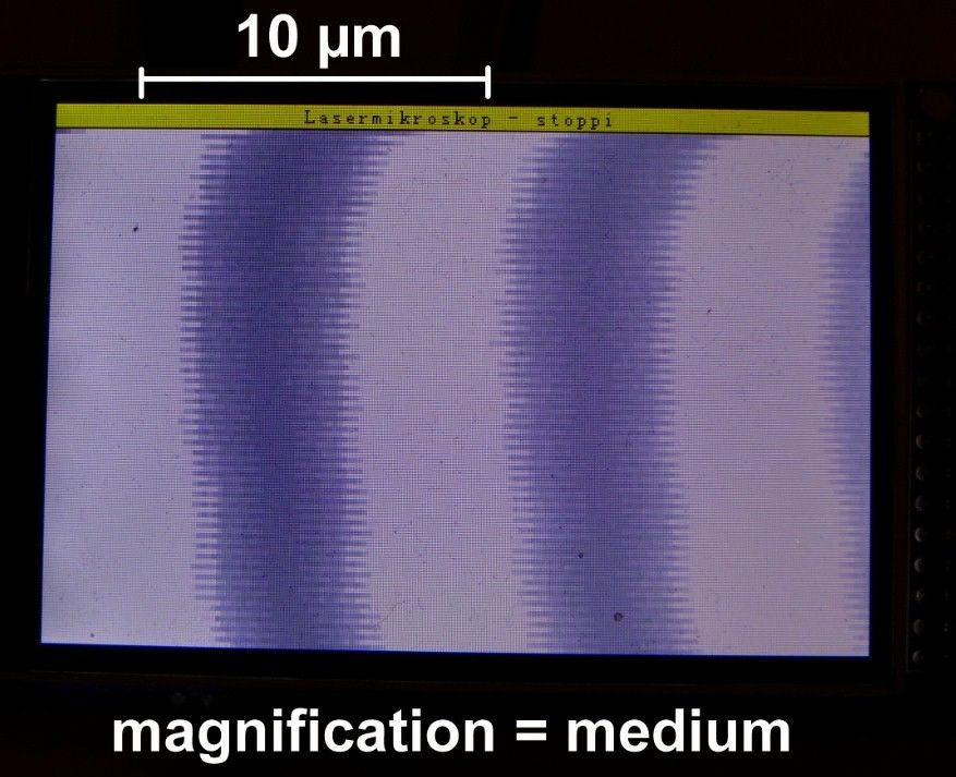 Using a calibration slide from eBay, [Stoppi71] calibrated the device for different magnifications. You can see the test slide at medium magnification. For the record, a human hair is about 40 or 50 microns thick. So the 10 micron mark in the photo would be like splitting a hair in quarters or fifths.
The real goal was to view pits on CDs, and the instrument is more than capable of doing that. The image doesn’t show up all at once (it is scanning, after all) and it isn’t the kind of view you’d expect from an optical microscope, but a typical optical scope can’t resolve below about 200 0.2 microns. Special techniques can push that lower, but being able to resolve things at the one or two micron level with something this simple is a great accomplishment.
We recently saw a different-looking LSM built on a conventional microscope stage and a DVD drive. If LSM isn’t enough for you, maybe you should pitch in on the open source electron microscope project.


Hackaday please learn to proof read stuff. “For the record, a human hair is about 40 or 50 microns thick. ” Humans can typically resolve a human hair by eye. Then you claim “but a typical optical scope can’t resolve below about 200 microns. ” I assume you mean 200 nanometers is the limit of traditional optical microscopy (depends on wavelength of light etc). Please re read what you write and do a sanity check.
The use of loudspeakers is interesting, the next step would be designing a purpose built voice coil assembly to move the sample or re purposing the voice coil assembly from hard disc drives.
+1 good Hack
Good catch on the micron/nanometer.
I am wondering what is limiting the resolution. I thought this would be an ‘easy’ way to 1/4 wavelength resolution microscopy.
I suspect its due to the resolution of the DACs used. If the max displacement of the speaker is ~2mm and the resolution of the DAC is 1024 (guess) then you will get ~ 0.0019mm or 1.9μm per a step.
It’s a 12bit DAC and therefore in the 240×154 Pixel mode I make steps with the width of 17… So concerning the DAC I could increase the Resolution much more. The limiting factor is the diffraction of light ;-)
Exactly, Resolution is diffraction limited (Abbe’s Law: minimum distance between resolvable light sources = (wavelength of light/ 2 times the Numerical Aperture of the objective lens). On a Confocal LSM you can actually get better resolution than this by closing down the confocal pinhole but because this samples only the center of the Airy disk, the reduction in light gathered leads to pretty bad SNR usually (unless you are lucky and have either a very reflective or a very fluorescent sample).
Very cool! I wonder if it would produce better images if all the scan lines were done in the same direction instead of alternating. Or by just shifting every other line over by some adjustable amount, which would probably improve quality without slowing down the imaging.
good point
Or using some deinterlacing code.. like bob deinterlacing?
Amazing project though
good idea, i’ll going to prove that…
That bidirectional jitter should be correctable by scanning only one direction. This was a problem on early dot matrix printers, which had a unidirectional high quality print mode. Or perhaps the images could do a software “vertical sync correction” (ofset and gain) to realign to opposing direction scanlines. Speakers are not necessarily symetrical on push and pull directions, and also the motion amplitude is sensitive to coil temperature, so could benefit from thermal compensation. IMHO…
What are people trying to accomplish with LSM anyway? You aren’t going to get any better resolution than you get with an ordinary microscope: it’s limited by the wavelength of the light and the numerical aperture of the lens, laser or no frickin laser.
What you get with laser scanning is a very slow way to get a mediocre image, and a good way to thermally damage your sample at the same time.
Instead, use a cheap webcam, and you can scan & stitch *that* and get a huge, high resolution image quickly, AND you get to play with all kinds of alternate illumination schemes: brightfield, darkfield, phase contrast, multispectral, light sheet, fluorescence, polarized, etc… Much more versatile, and much better imaging. But maybe less nerd cred because no lasers needed.
The possibility of 3D scans and lots of useful data from the scans. http://www.olympus-global.com/en/news/2004a/nr040326ols3e.jsp
That link describes a confocal microscope. The laser-scanned microscopes recently described here aren’t much like that at all. Without the additional parts required in the optical chain in a confocal microscope (principally the detector pinhole), it’s barely a cargo-cult imitation: you’d be much better off doing conventional microscopy and Z-stacking to get the 3D image.
(I have worked with 3D confocal laser-scanned images since 1987, but I’ll grant that back then it required an optical table full of parts, a gas laser, a rackful of equipment to run it all, and a $120,000 Sun workstation to visualize the 3D data.)
CDs, DVDs and BluRay systems basically !are! specialized confocal microscopes. If your sensor is a tiiny phototransistor, then it effectively is a spatial filter, just like a pinbole.
Why he did’t use the built in voice coils in the optical read-head is beyond me.
As fsr as 3d imaging, you can do a pretty good job with holographic microscopes. Not hsrd to build, although you need a very small pinhole to get a good spherical wave, and you need as many bits as possible (more contrast means better reconstruction). But you don’t need lenses …
It’s just a cute “hacker” type project that involves frickin lasers. It’s fun.
>What are people trying to accomplish with LSM anyway?
Are you a party pooper or are you just jeallous :)
Party pooper, I guess. Not in the spirit of what this should all be about. I’m sorry.
It really is a cool and fun little hack. Kudos to Stoppi et al. I’m sure it was a good and fun learning experience.
“and a good way to thermally damage your sample at the same time”
That’s seems silly, a sample always needs light regardless, optical needs even more light, and I doubt the energy of the IR laser-diode is enough to heat up much when not in ‘write’ mode
It might sound silly, but when you focus even a tenth of milliwatt of laser power to a diffraction-limited spot of (say) a square micron area, that’s a power density of a hundred megawatts per square meter: hotter than the surface of the sun!. When you loiter around with the slow scan speeds used here (instead of a rapidly-spinning CD surface) that can cause *really* intense local heating.
Google squeezed light. Years ago a technique to optically image stuff smaller than the wavelengths of light was developed. The very basics of it involved “squeezing” light through a “funnel” with an opening having a diameter narrower than the wavelength of the light beam going through it.
Yeah OK, that’s not how physics works.
Yes, physics works that way. It’s all what you trade off for it. Depth of field and throughput take a big hit in return for resolution.
It’s real, and has been for some time. 1972: http://www.nature.com/nature/journal/v237/n5357/abs/237510a0.html
ObWikipedia: https://en.wikipedia.org/wiki/Near-field_scanning_optical_microscope
This is the kind of project that gets my interest in things. Thanks for doing the technical work and thanks to Hackaday for sharing it with us. It’s really great that a group with such a wide and deep understanding of science is sharing ideas. The hacking aspect is what separates people that do things from people that just talk about things. I’m really impressed with this (and the confocal microscope previously linked to) work. Keep at it!
Thank’s John. I always start my projects with a great curiosity and the will to realize complicated scientific things with simple methods ;-)