Ever wanted to access a file or run some program on your computer while away from home, but the darned thing is turned off? Finding themselves occasionally working away from home and not wanting to leave their computer on for extended periods, [robotmaker]’s solution was to hack into existence a WiFi-controlled power bar!
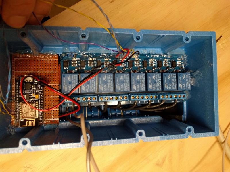
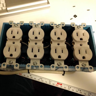 Inside the junction box, an eight-channel relay is connected to an ESP8266 module. The module uses MQTT to communicate with Home Assistant and is powered by a partially dismembered USB AC adapter — wrapped in kapon tape for safe-keeping. The entire bar is wired through a 10A fuse, while also using a fire resistant 4-gang electrical box. Once the outlets were wired in, closing it up finished up the power bar.
[robotmaker] controls the outlets via a cheap smartphone — running HADashboard — mounted to a wall with a 3D printed support. Don’t worry — they’ve set up the system to wait for the PCs to power down before cutting power, and the are also configured to boot up when the relay turns on.
The best part — the power bar only cost $25.
[via /r/homeautomation]


Why not use the feature for this backed into every computer I’ve owned for the last 10+years: Wake-on-LAN?
WOL consumes a little more power … but yes, it’s what I use.
I have 3 computers at home, one of them supports wake on lan via ethernet, but because it’s connected via wifi, I can’t use it. The other two don’t support it (ironically, the one that does is the *oldest* of the 3). At my office, just taking a quick survey of desktops (all of our servers support it), only about half of the desktops support it. So yeah, there’s still a usable scenario.
Also I’ve actually been working oddly enough on almost this exact setup for a client (4 outlets, instead of 8, and at the last second I stopped the esp8266 order to put it on hold for a pi zero w because building some of the intelligence into the device is a huge bonus). None of the devices that will be connected to it are traditional computers, what’s more, they are all embedded systems (network camera system, some network equipment) that only has a remote reboot if it’s responding. Where it’s located at means that if it’s not responding, they’ve got a long wait for me to get over, borrow keys to get through multiple locked doors, 9 times out of 10, just to power cycle a wireless AP.
Seems a better idea to remotely use the computer on switch for turning it on too instead of switching the power.
On the other hand it does have a certain allure to be able to control power like that.
Seems like an even better idea would be to use the Wake On Lan feature if it is available, no modification necessary beyond tweaking a BIOS value? I have seen controllable rack mount power strips so there must be some scenario where this could be useful. Maybe if you needed to reboot a faulty switch. Or to switch on/off something lacking an Ethernet port.
In my life I only once got WoL to work, but I tried many more times.
And yes I did enable it in the BIOS.
That’s why I would not immediately think of that solution, but perhaps it works fine for others and it was just something with my systems that was quirky.
Hmm.. it works fine for me. My desktop is an old cast-away Dell. I think it was marketed to be an office workstation. Not something where someone is likely to actually use the WoL feature. I turn it on from my Banana Pi which is also my file/web server so it doesn’t get shut off. It worked on the first try!
it is a black art, i have 98 desks. all identical machines with identical win7 SOE builds, 3 of them just refuse to WOL. i even flashed the BIOS, nothing.
Apart from the bios settings you also need to mess about with the PME settings and the network adapter settings.
from memory its
bios:
disable hard off
enable local nic chipset (or if you’re using a card you’ll need to mess about some more with wake on events)
enable WOL
windows: Power management
allow this computer to come out of standby
NIC settings
enable PME
let windows manage the power settings
wake on lan
wake on magic packet
or similar, i’m not near the machines at the moment.
when you get it working, it’s a fantastic sound to watch 100 computers all start up at ‘roughly’ the same time.
Yeah, if the machine’s crashed and you can’t just walk in there and hold the power button down to forcefully shut down, then being able to yank the cable remotely is a godsend.
Or just ssh to your router and use WoL to wake it up, Mikrotiks have a handy wol command.
It would be much much simpler to send a wake on Lan packet
Can you say “dirt-cheap home automation”? I knew you could…
Fauxmo!
http://tinkerman.cat/emulate-wemo-device-esp8266/
I know, I know just because but, wake on lan? Having said that I think I’m going to make one similar for not a computer.
That Is Cool! My private cloud!
I just recently built something similar but with Bluetooth instead of wifi.
getting the whole thing to fit seamlessly in a 4-gang box is a very nice touch.
Yes indeed, especially if you need several channels in the same spot.
I have a box of the Sonoff “ESP8266” single channel AC switches, but this is neat too.
This is one of the good ones! Very nice assembly!
Screw those AC wires down, don’t use the push-in terminals. Sure, they work, but I would not trust plugging a large load into the end of the daisy chain through multiple outlets. Always screw them down.
A physical insulating separator between the AC and low voltage compartments would be nice.
Sorry, sounds like I’m being critical… which is NOT the case. Gonna build my own.
I didn’t see it, but I hope there’s sufficient space and insulation between the low-voltage stuff and the outlet wiring. In other words, the normal cautions about working with AC wiring.
(this might be a good topic for a HaD column – where can today’s hackers find construction and safety guidelines for doing AC-connected projects?)
Not necessary if the device is wireless only as is the case here. For debugging, use an isolation transformer to be safe.
Those sainsmart relay packs have good isolation if you do your cable management correctly as the mains voltage side is all on one side of the pack, and lv (+5v) /data pins all on the opposite side.
And let’s not forget that when you create and use anything connected to AC you can save quite a bit of money, because you might as well cancel your fire insurance. Once an investigator finds something like this in the remains of a domestic fire — even if it was completely up to snuff and had nothing to do with the fire at all — your insurance will not pay a dime (or you’ll have a heck of a job convincing them otherwise).
You can pull up full NEC code on google.
Neat, I do similar with those sainsmart relay packs but I mount a arduino mega in a separate enclosure because I’m liking physical separation more like that and I have hardwired ethernet on my devices because old property, stone walls, unreliable wifi, and I send relay state changes to home-assistant using the JSON api rather than MQTT.
One day I’ll have to extend my principle to control individual outlets though once what I have has soak tested for a few more months, and I’ll probably make a similar enclosure but with some inner walls to keep it isolated.
I used a FTDI 245 something a couple of years ago. Works fine for turning the computers on and off. Turning the room fan on causes it to lose its mind though. Guess I need a (8) diode someplace. :-(
I was using IPMI modules for this to reset routers and switches remotely 15 years ago.
Two questions: Where did you get the code and can I have some?
The code/logic behind this is trivial…
This is supposed to be a constructive blog regardless of your condition.
Actually, Erik Johnson, wiring up LEDs and breaking a microwave is trivial…
Computers have off switches?
yep, my two favorites are garden hoses and 15 lb sledges. };->
that wiring deff is not 4 gauge idk how u would fit that into a socket…. the wiring in the pics looks like stranded crap…… hello fire
Neat project if you have some/most of the bits laying around. But the commercial versions are finally in the ~100$ range now: https://www.amazon.com/Auto-Ping-suppression-Over-current-protection-warranty/dp/B00EZWD146/ref=sr_1_2?ie=UTF8&qid=1488657517&sr=8-2&keywords=web+power+switch+7
paragraph 2 line 9
“— wrapped in kapon tape for safe-keeping.”
Isn’t that kap-T-on tape?
No, it’s the Chinese knock-off…
made from a castrated rooster
nice build u beat me to it.
Built a similar setup myself over the christmas holidays. Used a Raspberry pi (admittedly overkill for the purpose) and the same relay board, but mounted it in a 1U rackmount case. It’s connected to the lights in my flat, and provides five switched socket outlets as well.
https://scontent-lhr3-1.xx.fbcdn.net/v/t31.0-8/15724947_10157994664325022_3949333666863483803_o.jpg?oh=ae1f5c5fa290add74bd153a522121a6b&oe=59701C39
https://scontent-lhr3-1.xx.fbcdn.net/v/t31.0-8/15774983_10157993683915022_1714233017912120991_o.jpg?oh=b9659c4de390d9fef2f1d3c3f62f8089&oe=59322108
I like it but what if someone turns the socket off? A better idea might be to insert an esp8266 module into a wall socket box that could remotely manipulate the switch either electronically (by bypassing the hard switch or using a solenoid to flip the switch. Not sure how this would fly with building regs but seems like a more elegant idea.
I’m not trying to say this box isn’t good I like it just saying it could having been done differently.
I think replacing the hard switch with a relay and microcontroller is OK if there is a pushbutton switch which immediately toggles the switch state locally on the device.
Then the microcontroller can send a MQTT message back to the rest of the network to let that stuff know that this outlet has changed state, and a “remote control” from another MQTT device on the network can also flip its state.
But the local switch should always work like a “real” switch. Users expect that you press the button and that power outlet toggles state, every single time. The microcontroller should work reliably all the time, 24/7/365, and it should immediately toggle the relay state. If the WiFi AP goes down, or the MQTT broker goes down, or the cloud service or the LAN or outside internet pipe goes down at any point, the local switch should still always seamlessly work. (A common source of fail in these kinds of IoT appliances.)
When the network connectivity comes back up, the system may then “re-sync” the true state of the switch with what the rest of the system thinks the current switch state is.
(Although AS3000 requires a switch in the active line at every outlet, and similarly with other codes around the world, you may not be allowed to have no switch, if this is a fixed installation inside the wall outlet.)
Thats how my setup works, local hardwired switches with optoisolators on each one, it can still be operated remote via the network but if theyre used the device updates instantly and sends a message to home-assistant that the state has changed via its API to keep it in sync.
But it doesnt currently sync when the ethernet comes back up, as I have hardwired ethernet a power outage that saw ethernet loss generally reboots all the devices too as theyre POE, so then I’m into reading their last known good state and trying to restore it, or come up with all lights connected on for safety. Woke up to the house lit up after early hours brown outs a few times though so making a ups style poe psu :)
I did the project with a relays from Ali. They looked very similar to the SaintSmart ones. And I would bet on that all the know-how were “copied right” in this case. The project used RPi (3.3V on the IO) and this shield with 5V voltage for relays and 3.3V for GPIO signal (signals lighted LED when they are 0, so the other end of the LED should be connected to the 3.3V). And the sield was not functional because of the very low opto-led current. It was initially approx 1mA and according to the datasheet should be at least 10 mA. I tuned it a little bit until the functional state, but after a year, the opto-LEDs degrade so much, that I had to modify my device to supply real 10..15 mA there to make the optocouple working.
And I see there no snubber RC circuits. If once a time the author will put in the socket something like a fridge, drill, cooler, or something has a motor or inductance, the relay contacts will die very fast because of the inductive initiated discharges.