Linear voltage regulators are pretty easy to throw into a project if something in it needs a specific voltage that’s lower than the supply. If it needs a higher voltage, it’s almost just as easy to grab a boost converter of some sort to satisfy the power requirements. But if you’re on a mission to save some money for a large production run, or you just like the challenge of building something as simply as possible, there are ways of getting voltages greater than the supply voltage without using anything as non-minimalistic as a boost converter. [Josh] shows us exactly how this can be done using a circuit known as a charge pump to drive a blue LED.
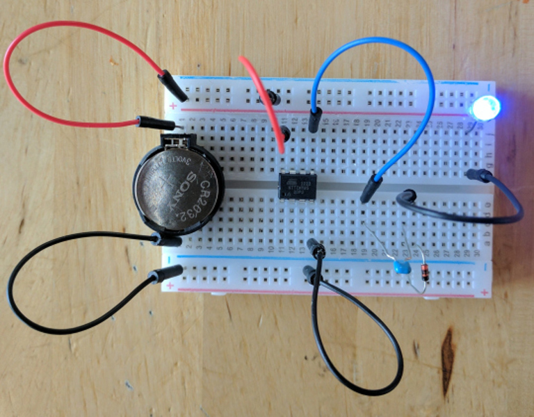
One of the cool things about AVR microcontrollers is that they can run easily on a coin cell battery and source enough current to drive LEDs directly from the output pins. Obviously enough, if the LED voltage is greater than the voltage of the power supply, this won’t work. That is, unless you have a spare diode and capacitor around to build a charge pump.
The negative charge pump works by charging up a capacitor that is connected to an AVR pin, with the other side between the LED and a garden-variety diode to ground. That results in a roughly (VCC – 0.7) volt difference across the capacitor’s plates. When the AVR pin goes low, the other side of the capacitor goes negative by this same amount, and this makes the voltage across the LED high enough to light up. Not only is this simpler than a boost converter, but it doesn’t need any bulky inductors to work properly.
Will this work for any load? Am I going to start any fires by overdriving the LED? Luckily, [josh] answers all of these questions and more on the project page, and goes into some detail on the circuit theory as well. Granted, the charge pump doesn’t have the fine control over the power supply that you can get out of a buck or boost converter (or any switch-mode power supply). But it does have good bang-for-the-buck.


Microcontroller controlled charge pumps are very useful for generating voltages for all sorts of things like lcds, leds and even creating negative voltages to get your low power op-amp to go to hard 0V
This has been used for years but in the days of $1 buck/boost/inverters you forget about things like this and when you are low on space or grinding on the edge of your budget they become quite useful!
+10 for thinking outside the box.
In some oscillator modes you can even use the clock output pin for voltage doubling.
Here’s some good reading from microchip – lots of useful tips.
ww1.microchip.com/downloads/en/DeviceDoc/01146B.pdf
ww1.microchip.com/downloads/en/DeviceDoc/40040C.pdf
Q: Wait, you are totally over-currenting that LED when the IO pin goes low! It is going to smoke!
A: Chill out. Remember that the IO pin is current limited in the chip. This limits how fast we can discharge the cap, which limits the current flowing though the LED. It is all going to be OK.
Wait what? While a cool hack. This guy is on crack when it talks about the EE pin aspect of the AVR. Those pins are not current limited, check the datasheet, it even specifies an “absolute maximum” rating for IO pins current.
They are usually much more forgiving then most other micro controllers, but they are not current limited and I’ve blown IO pins of AVRs. Which is why most likely the pin is surviving fine. But “it works for me” is not the same as “you can do this safely without problems”
Wanted to say the same. There is no current limit built in. The I/O simply has an output resistance that gets smaller as the supply gets higher. You can totally get more current from the pin than the absolute maximum rating.
The reasons why you don’t need a resistor here are 2 fold:
1. the battery used is pretty high internal resistance and will limit the current anyway
2. the actual charge pump (hence the name) can only pump a certain amount per charge, how much the cap can hold. Couple that with the operating frequency and you get the maximum current it can supply.
Is it just me or does no one else love trying to decipher double negatives like this… ‘without using anything as non-minimalistic as a boost converter’.
I don’t not know where you ain’t un-understanding.
I used to use these a lot when working with very small UHF transmitters. The nice thing about charge pumping is you can get a very consistent current draw on the battery.
When it comes to 1/3N batteries (which was the power source we were using at the time), slamming a battery with 700mA for a beep really hurts the projected mAh. By consistently pulling around 30 mA off the battery with your charge circuit you can just hit the capacitor.
I was going to ask if this could be used to drive a 2n7000 gate from a 3.3V IO… but then I realized that this doesn’t boost up – it boosts down, which wouldn’t work in the usual arrangement of a FET as a switch.. for the alternative approach, once you add that inductor&second FET, it’s no longer tiny and simple. Are there other options for this that people have used?
Use a P-channel ;)
Low power Voltage Doubler from a tristate output:
2 diodes and 2 capacitors
http://www.555-timer-circuits.com/voltage-doubler.html
Note that there are many Power MOSFET bridge driver chips that will handle >1A loads.
Use a FET with Vgs < 3.3V
Or a BJT
The circuit can be re-configured to boost *up*.
Interesting follow up from the same guy, on the same minimalism boost problem, still with an AVR:
https://wp.josh.com/2017/03/22/challenge-design-an-avr-controlled-boost-converter-using-only-one-part/
How I like those hacks, like that old tiny PIC12C RFID tag hack from an old Microchip contest (Design for dollars if I remember well) that used the protection diodes as a rectifier for the voltage generated by the tag reader on an external inductor which one side was connected to the clock input of the chip to clock it from the reader’s frequency of operation and the other side connected to an IO to clamp it and transmit data…brilliant! Saw it too but years later with an AVR on scanlime by Micah Elizabeth Scott.
If someone remembers and knows if source codes of this Microchip contest was ever published or if it was just proof of concept ideas…?
Thanks Google!
http://ww1.microchip.com/downloads/en/AppNotes/3_001.pdf
Thanks [Syl20]
A treasure trove link!