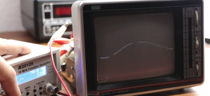
Do you still have an old analog CRT television lying around? With the advent of digital signals, analog TV´s are going to the dumpster or the recycling center. But you can still put them to good use, just as [GreatScott!] did, by converting the TV into a crude oscilloscope.
The trick is to take control of the two deflection coils that move the electron beam inside the CRT in the horizontal and vertical directions. The video describes in detail the process of identifying the coils and using an Arduino nano in combination with a DAC to amplify the input signal in order to get the waveform in the TV screen. Step by step explanations and great editing make this project delightful to watch.
Even if you do not follow [GreatScott!]´s steps to build a simple oscilloscope, don´t throw away that vintage TV!, it is a great source of analog parts. The flyback transformer can be used to make a high voltage power supply, and you also get some nice high voltage capacitors (both electrolytic and mylar ones), the horizontal output transistor which is a high voltage one, ferrite transformers, magnet wire, plus a lot of other small parts. Other uses for old TV sets that you may want to try is to convert your TV into a gaming console, or an audio synthesizer controlled by drawing with a light-sensitive pen on a CRT television.


My understanding has always been that magnetic deflection is too slow versus the electrostatic deflection used in CRT ‘scopes.
I’d be interested in knowing what sort of bandwidth can be realized here… just to satisfy my curiosity.
… not that many folks with even an inexpensive “real” scope ever come close to utilizing their full capabilities…
If you drive the coils based on current instead of voltage you can get a bandwidth limited by your max driving voltage and coil inductance. This and rewinding the coil can make a CRT useful for vector graphics.
Also tap into the electron gun driver circuits so you can turn them off and on.
Drive each with an 8bit DAC and you get a color vector display.
Audio frequencies. There were ads for plans in lots of magazines in the 60’s. IIRC 10-20KHz was claimed.
Yep. Did it several times way back when. Hooked it up to the left and right channels of my stereo and watched my music. My friends all thought I was some kind of nerd, but they spent a lot of time watching it. :D
Holy crap. I did this mod 40+ years ago when TV’s weren’t in any danger of going away. The idea came from some hobbiest magazine, like Radio or Popular Electronics. You leave the horiz section running to keep high voltage generation, use the vert deflection as horizontal sweep (turn the yoke 90 degrees), and drive the old horiz yoke (now vertical) with the signal you want to visualize. And yes, it was crude as hell, but still hugely better than not having a scope.
Yeah… as noted this was a common project and a staple at science fairs some 40+ years ago. It’s still kind of a fun hack but not that useful these days, when you can get little scope kits for like US$22 or assembled dual-trace units for around $100. But integrating an Arduino into the mix is a nice upgrade.
I figured it out without buying the plans back then. It got a high award in high school art/science fair, vector mode in stereo.
Let’s say you wanted to keep the HV section running and drive the H & V coils totally externally. Would it be enough to find an inductor of the same inductance and resistance/reactance and sub that in on the H connection, so the flyback would continue to run? The V coil usually isn’t part of the HV circuit, right?
I guess the resistance alone woukd do the trick
Poor Man’s O-Scope back in the day but few went farther than just the first lissajous pattern. Was one of the “rights of passage” projects like the 555 was 20 yrs ago.
To get better bandwidth (maybe up to a Megahertz), L/R constant could be changed with resistor in series with the coil(s). Similar schemes were used to get faster response out of stepper motors.
Ha, I did this when I was a kid, but I just turned the TV sideways and used the vertical scan. That meant the scan frequency was fixed, but it kind of worked.
As stated, this is a way old hack, and it sucked back than and it still sucks now. Good for audio frequencies. Better off using a soundcard and an old PC, or just pick up a decent old analog scope. You should be able to pick up a 60-100Mhz dual trace scope for under $20 if you shop around a bit. You will pay more for decent probes.
I’m interested in this subject but sitting through an eight minute long Youtube video for a project that barely does what it set out to do is unimpressive. How hard would it have been to explain this on a webpage instead of dragging it out to eight minutes? I really don’t need to see him blunder through impedance issues and trying to drive a CRT yoke from a function generator.
Magnetic deflection to generate “oscilloscope” images is doable. Old arcade games used magnetically driven XY displays for games like Tempest, Asteroids and Star Wars. The HV section has to work independently of the yoke so either you have to supply an extra inductor to replace the yoke or design the flyback circuit so it doesn’t need the yoke. Atari used the latter for their XY monitors. Some VGA multisync CRTs had an independent HV circuit and those might be convertible to an XY display.
If you want a color vector display that is good for more than just sine waves check out this link on UKRGVAC http://www.ukvac.com/forum/the-amplifergifone-tx14v-vector-monitor_topic331866_page1.html
Somebody modified an old television to work as an arcade vector monitor.